Quantcast
Channel: Ken Shirriff's blog
Viewing all 314 articles
Browse latest View live

Reliable after 50 years: The Apollo Guidance Computer's switching power supplies

$
0
0

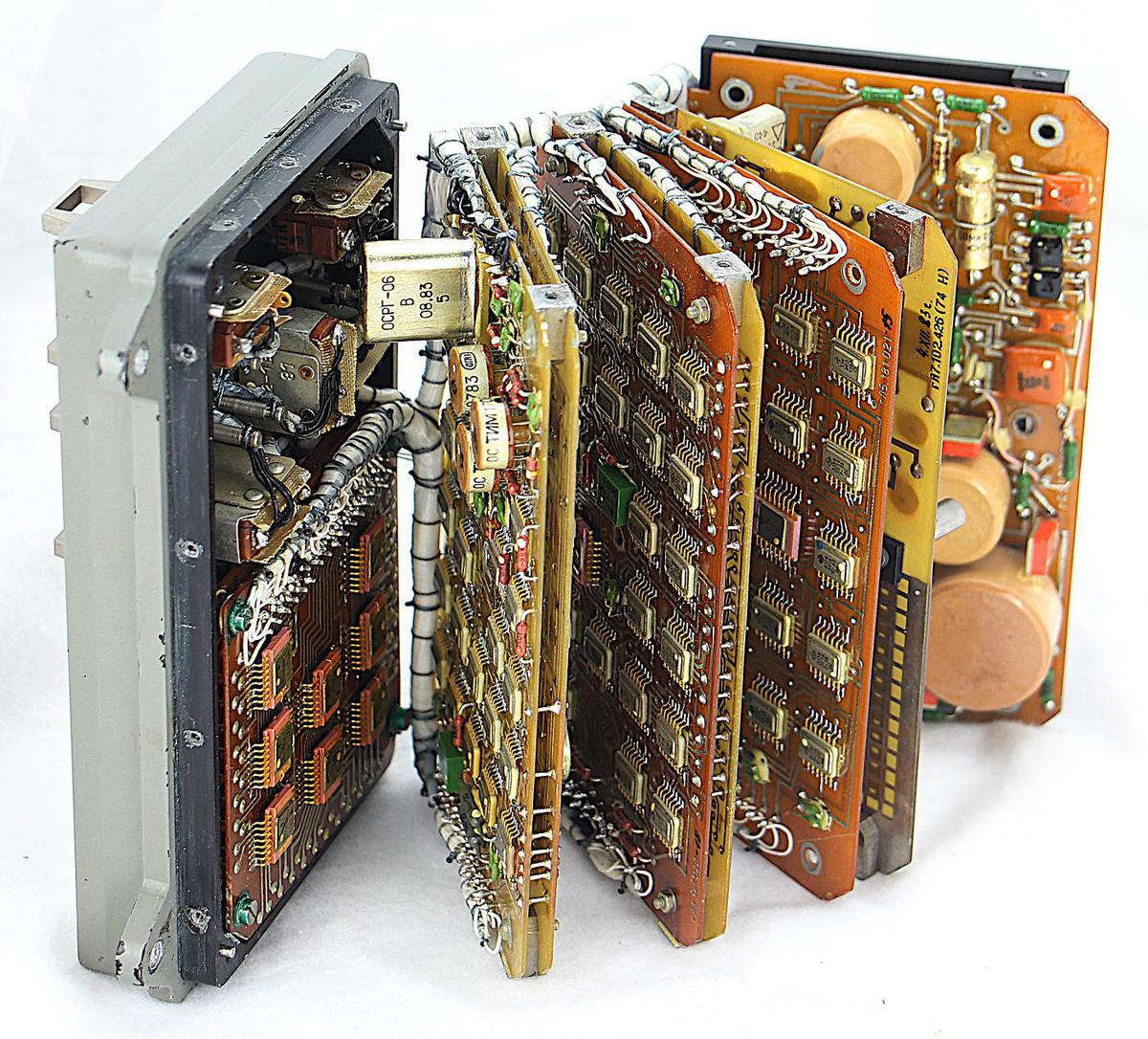
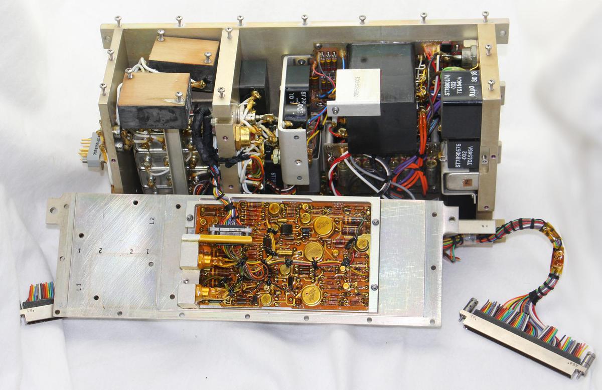
We recently restored an Apollo Guidance Computer, the revolutionary computer that helped navigate to the Moon and land on its surface.1 At a time when most computers filled rooms, the Apollo Guidance Computer (AGC) took up just a cubic foot. This blog post discusses the small but complex switching power supplies that helped make the AGC compact enough to fit onboard the spacecraft.

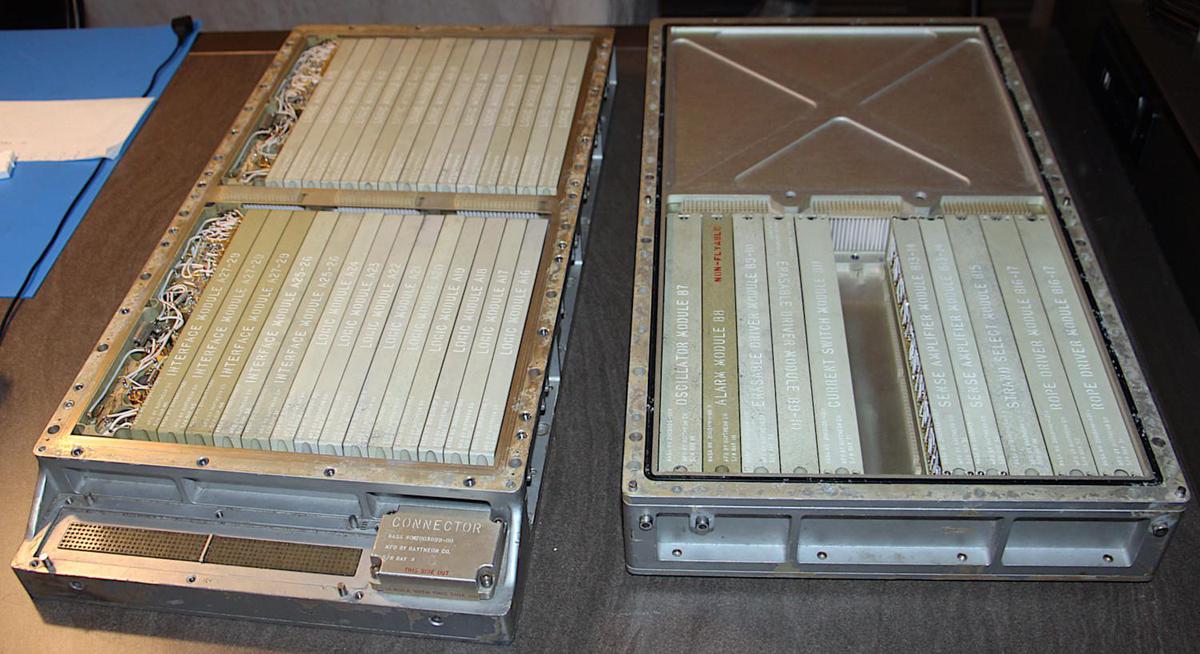
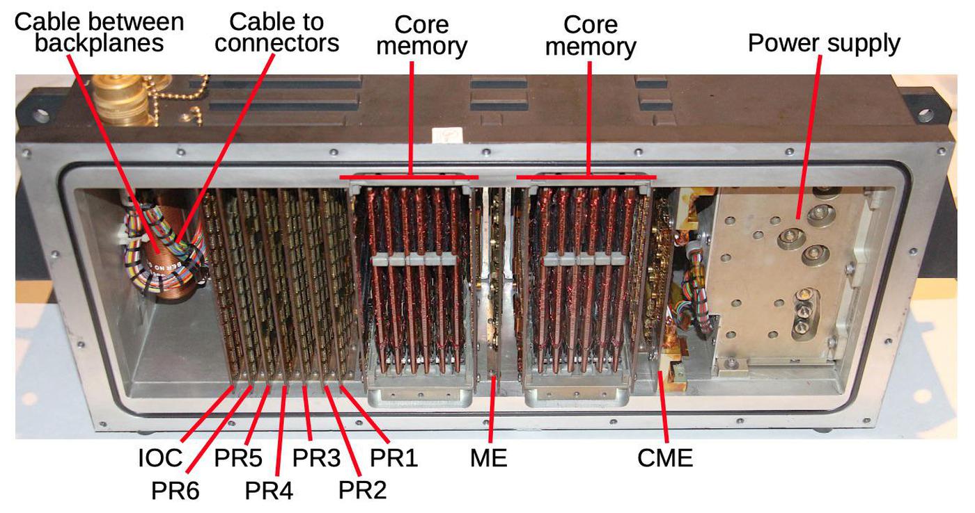
Inside the Apollo Guidance Computer. The power supplies are the tangles of wires on the far left.

Inside the Apollo Guidance Computer. The power supplies are the tangles of wires on the far left.

The photo above shows the Apollo Guidance Computer after separating its two trays. Tray A on the left holds the logic and interface modules, while Tray B on the right has the memory circuitry. The AGC has two power supplies in Tray A on the far left: a +4V power supply and a +14V power supply; the power supplies look like a tangle of wires in the photo. The logic circuitry, entirely built from NOR gates, was powered by 4 volts. The interface circuitry and memory used the 14 volt supply.

The spacecraft generated 28 volts from fuel cells, which combined hydrogen and oxygen to produce both water and electricity.3 The task of the power supplies was to convert the spacecraft's 28 volts into the 4 and 14 volts required by the computer.2 The 4-volt power supply could output about 10 amps (i.e. 40 watts) while the 14-volt power supply could output about 5 amps (i.e. 70 watts).4 Thus, the power supplies are roughly equivalent to laptop chargers (although a laptop charger deals with more challenging AC line voltages).

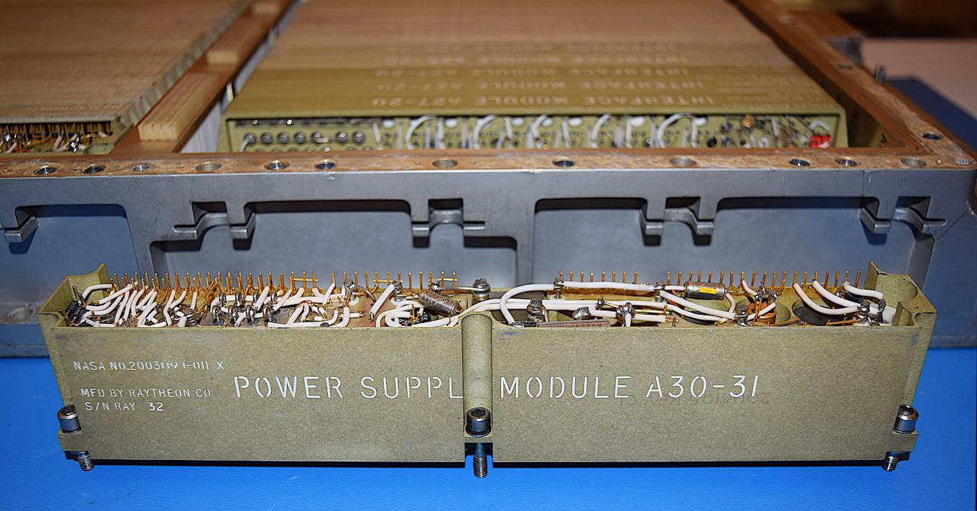
The power supply module in front of the AGC. The module in position A30 provides +14 volts, while the (identical) module in position A31 provides +4 volts.

The power supply module in front of the AGC. The module in position A30 provides +14 volts, while the (identical) module in position A31 provides +4 volts.

Cordwood construction

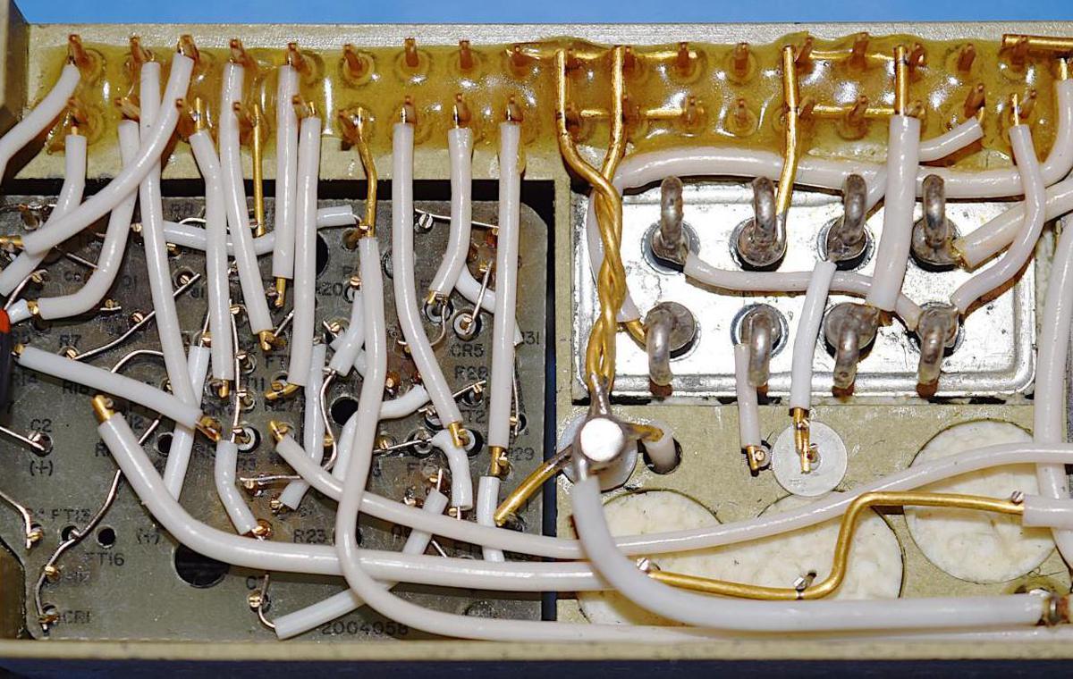
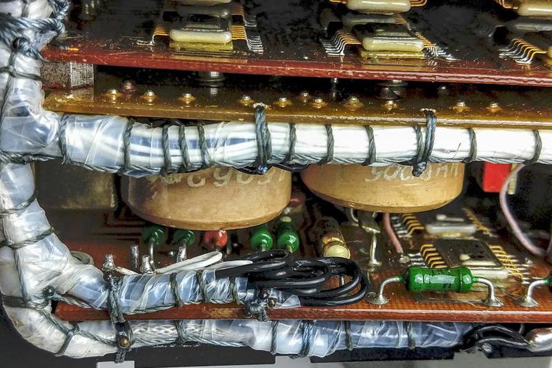
The power supplies, like the AGC's other non-logic modules, were built with cordwood construction. In this high-density technique, cylindrical components were inserted into holes in the module, passing through the module, with their leads exiting on either side.6 The left side of the photo below contains resistors, capacitors, and diodes. Because of the cordwood construction, the components are not visible except for the ends of their leads poking through holes. Point-to-point wiring connected the components with welded connections. (The other side of the module is similar, connecting the other ends of the components.) The shiny rectangle on the right is a relay, used to shut off power for standby operation. The ends of large filter capacitors are visible below the relay.

Cordwood construction in the power supply. On the left, components are mounted vertically through the module, 
with welded wiring on both sides. The metallic box on the right is a relay. Underneath the relay, the ends of filter capacitors are visible.

Cordwood construction in the power supply. On the left, components are mounted vertically through the module, with welded wiring on both sides. The metallic box on the right is a relay. Underneath the relay, the ends of filter capacitors are visible.

Cordwood construction was used for high density in applications from aerospace to Cray's CDC 6600 computer. For flight, the AGC's cordwood wiring was encased (potted) in epoxy, protecting it from vibration.

How the power supplies worked

Because the power supplies needed to be lightweight and efficient, they were switching power supplies, an unusual technology for the time. Most computers back then used linear power supplies, which were simpler but much too inefficient for the AGC since excess voltage is turned into waste heat.5 A switching power supply, on the other hand, switches the input voltage on and off at a high frequency. This yields the desired output voltage with very little wasted energy.

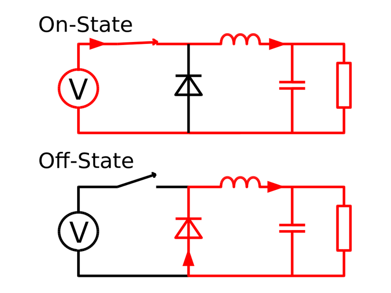
The AGC's power supplies used a common switching circuit called a buck converter, which converts an input voltage to a lower voltage. The diagram below shows the key components: a switch (transistor), inductor, diode, and capacitor. The key idea is that if the switch is closed for more time, more of the input voltage will appear across the load. Thus, the output voltage is controlled by the switch timing. The inductor stores energy and releases it when the switch is open, producing a relatively stable output.

A buck converter rapidly switches between the on state and the off state.
When on, current flows from the voltage source (V) through the switch and inductor to the load (right). When the switch is open, stored energy in the inductor continues to provide current to the load, through the diode. (Source:
Cyril Buttay,
CC BY-SA 2.5).

A buck converter rapidly switches between the on state and the off state. When on, current flows from the voltage source (V) through the switch and inductor to the load (right). When the switch is open, stored energy in the inductor continues to provide current to the load, through the diode. (Source: Cyril Buttay, CC BY-SA 2.5).

A switching power supply requires a complex control mechanism to switch on and off at the right time. The AGC used a technique called PWM (pulse-width modulation), where power is switched on and off at a fixed frequency (e.g. 20 kilohertz), but changing the fraction of the time the power is on to regulate the voltage.

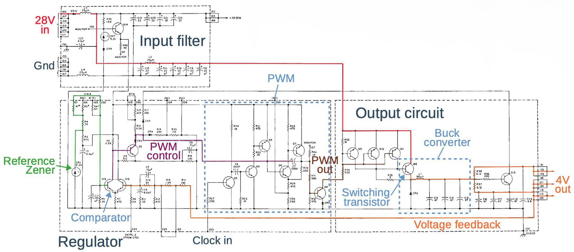
The schematic below shows the AGC's power supply. (Don't worry about reading the details; click for a larger version.) The buck converter itself (outlined in the lower right) has the expected switching transistor, diode, inductor, and capacitors. However, the power supply has many more components to implement the PWM control circuitry.

Schematic of the AGC's power supply. The main signals are highlighted: 28-volt input (red), 4-volt output (orange),
reference voltage (green), comparator output to control the PWM (purple), and PWM output (brown).
(source)

Schematic of the AGC's power supply. The main signals are highlighted: 28-volt input (red), 4-volt output (orange), reference voltage (green), comparator output to control the PWM (purple), and PWM output (brown). (source)

To summarize the power supply's operation, 28 volts (red) is supplied at the upper left and filtered. The buck converter in the output circuit (right) reduces the voltage to 4 volts (orange) On the control side (left), the output voltage is used for feedback. A two-transistor comparator (lower left) compares the output voltage with a reference voltage (green) set by a Zener diode and resistor network. The output of the comparator (purple) goes through the PWM control circuit where it modifies the width of the pulses (brown) produced by the PWM circuit. These pulses drive the switching transistor in the buck converter, closing the feedback loop. The computer's clock signal providing timing for the PWM circuit.7

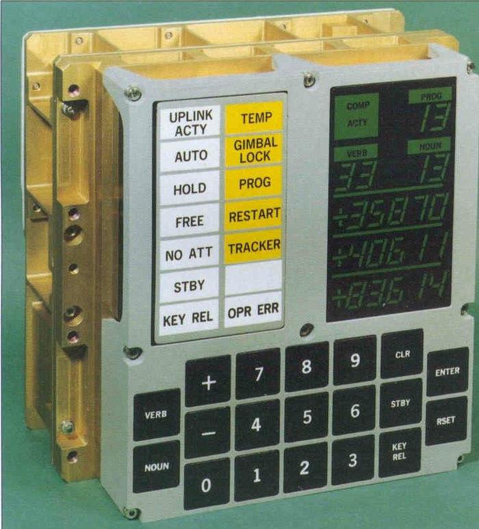
Astronauts interacted with the AGC through the Display/Keyboard (DSKY).
The STBY button (lower right) put the computer in standby mode, which was indicated via the STBY light (left).
Photo from Virtual AGC.

Astronauts interacted with the AGC through the Display/Keyboard (DSKY). The STBY button (lower right) put the computer in standby mode, which was indicated via the STBY light (left). Photo from Virtual AGC.

The power supply also included a standby circuit. By pressing the STBY key on the display/keyboard (DSKY), a relay would disconnect most of the computer's power. This reduced energy consumption when the computer wasn't needed.8

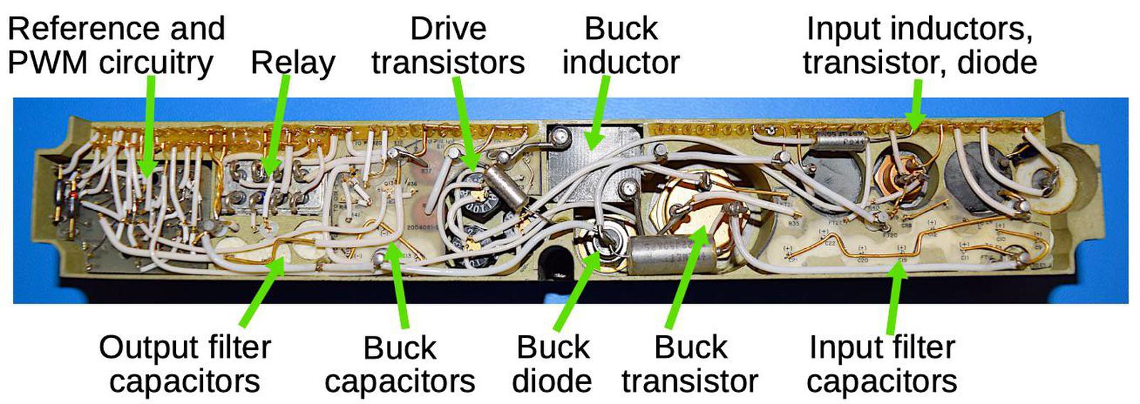
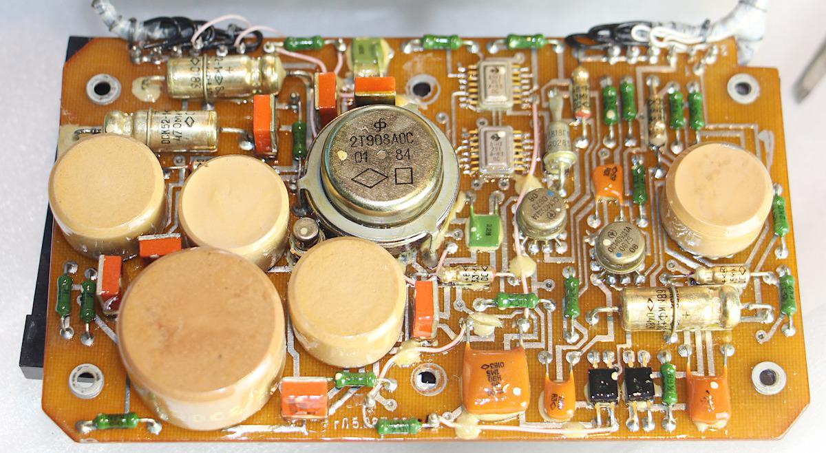
The diagram below shows the top of the power supply module with the major components labeled. Note the large size of the transistors, inductors and filter capacitors compared to the tightly-packed cordwood circuitry on the left. The switching transistor for the buck converter is almost an inch in diameter.

The major components of the AGC's power supply. The components for the buck converter are much larger than the control circuitry.

The major components of the AGC's power supply. The components for the buck converter are much larger than the control circuitry.

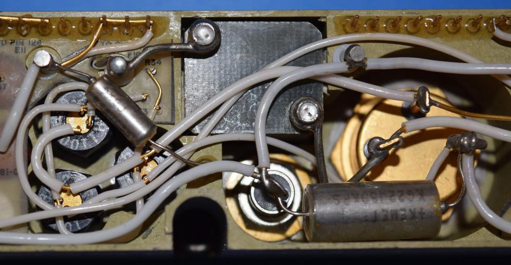
The transistors of the 1960s were barely able to support switching power supplies since they required a power transistor that could operate at both high speed and high current, which was difficult at the time. (Modern transistors (MOSFETs) are cheap and can handle much higher voltages, leading to ubiquitous low-cost phone and laptop chargers that run off an AC outlet.) The switching transistor required a high-current control signal, which was provided by three drive transistors (in a "complementary Darlington" configuration).

Closeup of transistors in the power supply.
The large transistor on the right is the high-current switching transistor.
Driving it required the three transistors on the left.

Closeup of transistors in the power supply. The large transistor on the right is the high-current switching transistor. Driving it required the three transistors on the left.

Testing the power supply

We extensively tested the AGC's components before powering up the system. For the power supply, we first checked all the tantalum capacitors since tantalum capacitors are prone to shorting out. We found that the capacitors were all in good shape with the proper capacitances. This is in contrast to modern capacitors, which often leak or fail after a few years. NASA used expensive aerospace-grade capacitors and X-rayed each one to test for faults, and this made a large difference.

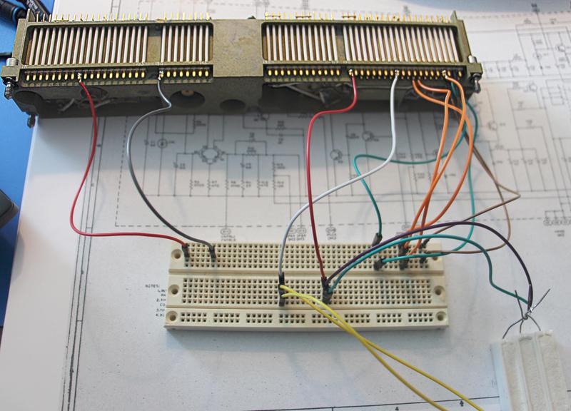
Wiring up each power supply for testing (below) was more complex than you might expect. The AGC used two identical power supplies that supplied 4 or 14 volts. The output voltage was selected by backplane wiring that connected different resistors in the feedback resistor network. We reproduced these connections on a breadboard, as well as connecting up the input and output. Some high-wattage resistors (lower right) served as the load.

The setup we used to test the power supply. Connections were made to the pins on the bottom of the module.
These pins connected the module to the rest of the AGC.
In this view you can see the white wires on the side of the module that connected the circuitry on top of the module to the pins on the bottom.

The setup we used to test the power supply. Connections were made to the pins on the bottom of the module. These pins connected the module to the rest of the AGC. In this view you can see the white wires on the side of the module that connected the circuitry on top of the module to the pins on the bottom.

We powered-up the AGC modules with 28 volts using a current-limited supply to limit potential damage from any faults. We took measurements and found that 4V power supply produced 4.09 volts while the 14V power supply produced 14.02 volts. The quality of the power was good, with about 30mV of ripple. We were somewhat surprised that both power supplies worked flawlessly after 50 years.

Conclusion

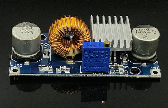
The Apollo Guidance Computer used advanced switching power supplies that were lightweight and efficient. While switching power supplies were exotic in the 1960s, improved semiconductors have made them cheap and ubiquitous. Now the switching transistor, a high-precision voltage reference, and the control logic can be combined on a single chip. The modern equivalent of the AGC's power supply is a tiny 5A buck converter for $1.50 on eBay (below). While I wouldn't trust this converter to get to the moon, let alone still work 50 years from now, it illustrates the dramatic improvements in switching power supply technology. (I've written more about the history of switching power supplies.)

A modern 5A buck converter is compact and costs $1.50.

A modern 5A buck converter is compact and costs $1.50.

To learn more about our AGC restoration, see Marc's series of AGC videos; the video below shows us testing the power supplies. I announce my latest blog posts on Twitter, so follow me @kenshirriff for future articles. I also have an RSS feed. Thanks to Mike Stewart for photos.

Notes and references

  1. The AGC restoration team consists of Mike Stewart (creator of FPGA AGC), Carl Claunch, Marc Verdiell (CuriousMarc on YouTube) and myself. The AGC that we're restoring belongs to a private owner who picked it up at a scrapyard in the 1970s after NASA scrapped it. For simplicity, I refer to the AGC we're restoring as "our AGC". 

  2. The first version of the Apollo Guidance Computer was known as Block I. The AGC was extensively redesigned to produce the Block II version that was flown. The Block I used +3V and +13V power supplies, while the Block II used +4V and +14V. The Block I power supply is documented here in section 4-8.7. The Block II power supply is documented here in section 4-5.9. 

  3. The power systems were different between the command/service module and the lunar module. On the command/service module the 28 volts was fed to the different parts of the spacecraft using two buses (Main A and Main B) for redundancy. Main A bus was connected to the A31 power supply module, while the Main B bus was connected to the A30 power supply module (schematic). The two buses were tied together inside the AGC after passing through power rectifiers, so either bus could power the AGC.

    (You may recall from Apollo 13: "Houston, we've had a problem. We've had a Main B Bus undervolt". When the oxygen tank exploded, the voltage from the fuel cells dropped, triggering the low voltage alarm.)

    The lunar module used batteries for its 28 volt supply, rather than fuel cells. Instead of Main Bus A and Main Bus B, the lunar module had a Commander bus (CDR BUS) and a Lunar Module Pilot bus (LMP BUS). The AGC on the lunar module was only connected to the CDR BUS, so there wasn't redundancy. 

  4. I estimated the wattage of the power supplies by looking at the current-limit feature. The power supplies have two 0.12Ω current-sense resistors. The voltage drop across these resistors will turn on transistor Q13, which will reduce the PWM output and thus the power supply's output voltage. The 4V power supply has the two resistors in parallel (connected by external wiring). Assuming the transistor turns on at 0.6V, this corresponds to a current of 0.6V / 0.06Ω = 10 A. The 14V power supply uses one current-sense resistor, so it will be limited to around 0.6V / 0.12Ω = 5A. 

  5. Some calculations show the problem with using a linear power supply. The AGC's power supply produced 4 volts at 10 amps, which is 40 watts. A linear power supply would dissipate 24 volts (of the 28 volts) at 10 amps, i.e. 240 watts. The linear power supply would be 14% efficient, wasting 86% of the energy. When you need tanks of liquid hydrogen and oxygen to provide the energy, wasting 86% is unacceptable. In addition, disposing of waste heat on a spacecraft is difficult, so an additional 240 watts would be a problem. 

  6. In the power supplies, the cordwood components are mounted differently from the other cordwood modules. Most AGC modules had components running from one side to the other as shown below, while components in the power supply went from top to bottom, parallel to the pins. This allowed the use of longer components, in particular, the large filter capacitors.

    Most of the cordwood modules, such as this interface module, had components running from side-to-side through the module.

    Most of the cordwood modules, such as this interface module, had components running from side-to-side through the module.
  7. One interesting thing about the power supply is that the PWM circuit was driven by the computer's oscillator. But the oscillator was powered by the power supply, raising a chicken-and-egg problem of how the system started up. The solution was that the PWM circuit would self-oscillate at 20 kilohertz if there was no external clock signal, so it would still produce the correct output voltage. Once it provided power to the oscillator module and the oscillator produced a clock signal, the power supply synchronized to this clock signal (50 kilohertz for the 4V supply and 100 kilohertz for the 14V supply). 

  8. The standby (STBY) key on the DSKY was changed to PRO (proceed) on later versions of the DSKY and the functionality was changed somewhat. 


Risky line printer music on a vintage IBM mainframe

$
0
0

At the Computer History Museum, we recently obtained card decks for a 50-year-old computer music program. Back then, most computers didn't have sound cards but creative programmers found a way to generate music by using the line printer.2 We were a bit concerned that the program might destroy the printer, but we took the risk of running it on the vintage IBM 1401 mainframe. As you might expect, music from a line printer sounds pretty bad, but the tunes are recognizable and the printer survived unscathed.1

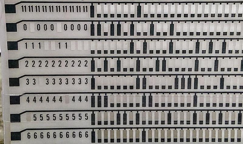
The IBM 1401 business computer was announced in 1959 and went on to become the best-selling computer of the mid-1960s, with more than 10,000 systems in use. A key selling point of the IBM 1401 was its high-speed line printer, the IBM 1403. By rapidly rotating a chain of characters (below), the printer produced output at high speed (10 lines per second) with excellent print quality, said to be the best printing until laser printers were introduced in the 1970s.

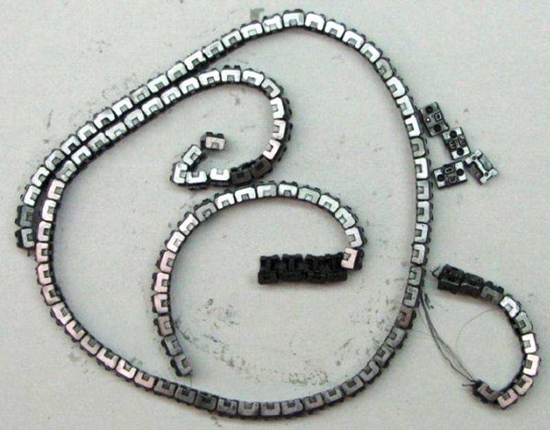
The type chain from the IBM 1401's printer. The chain has 48 different characters, repeated five times.

The type chain from the IBM 1401's printer. The chain has 48 different characters, repeated five times.

Line printers produced a lot of noise, but programmers soon discovered that by printing specific lines of characters, the noise had specific frequencies. It was possible to play a tune by printing the right lines for each note. Around 1970, computer scientist Ron Mak coded up some songs on punch cards using an earlier music program. He recently came across his old programs and gave us the opportunity to try them out.

How the line printer works

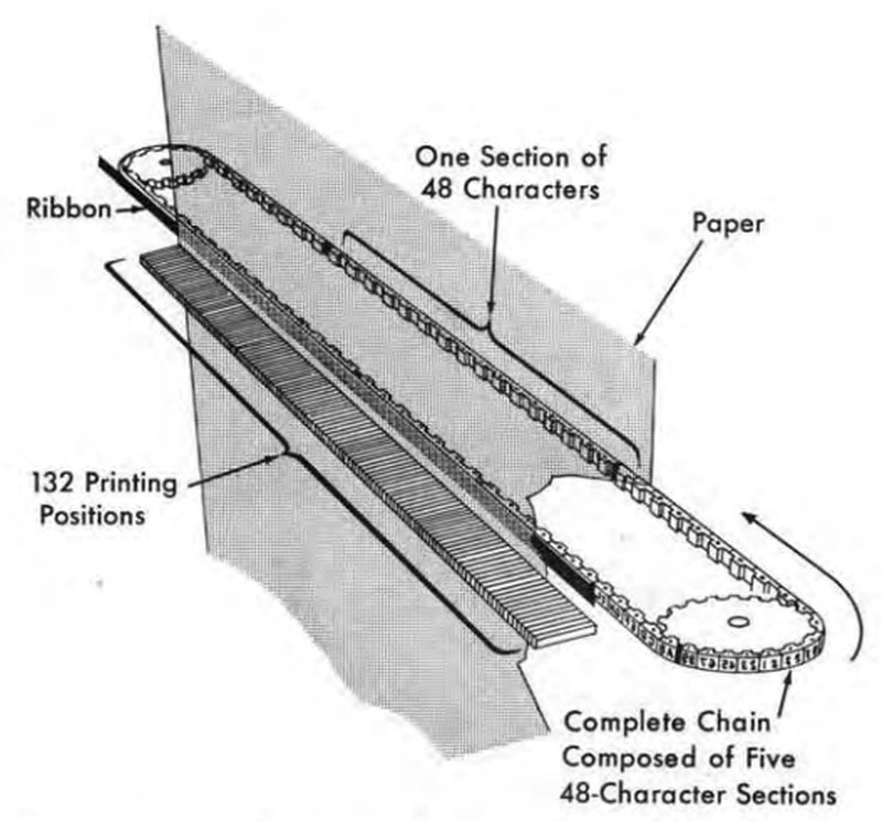
To print characters, the printer uses a chain of type slugs that rotates at high speed in front of the paper, with an inked ribbon between the paper and the chain. The printer produces 132-column output so each of the 132 print columns has a hammer and an electromagnet. At the right moment when the desired character passes the hammer, an electromagnet drives the hammer against the back of the paper, causing the paper and ribbon to hit the type slug, printing the character.

Printing mechanism of the IBM 1401 line printer. From 1401 Reference Manual, p11.

Printing mechanism of the IBM 1401 line printer. From 1401 Reference Manual, p11.

The printer required careful timing to make this process work. The chain spins around rapidly at 7.5 feet per second and every 11.1 µs, a print slug lines up with a hammer. The control circuitry has just enough time to read that position's character from core memory, compare it to the character under the hammer, and fire the hammer if there is a match. After 132 time intervals, each hammer has had an opportunity to print one character; this is called a "scan".3 Since there are 48 characters in the character set (no lower case), this process must be repeated 48 times so all the characters can be printed in any column.54 During each scan, the chain moves by just a single character's width6, so at the end of a scan it is lined up for the next scan.

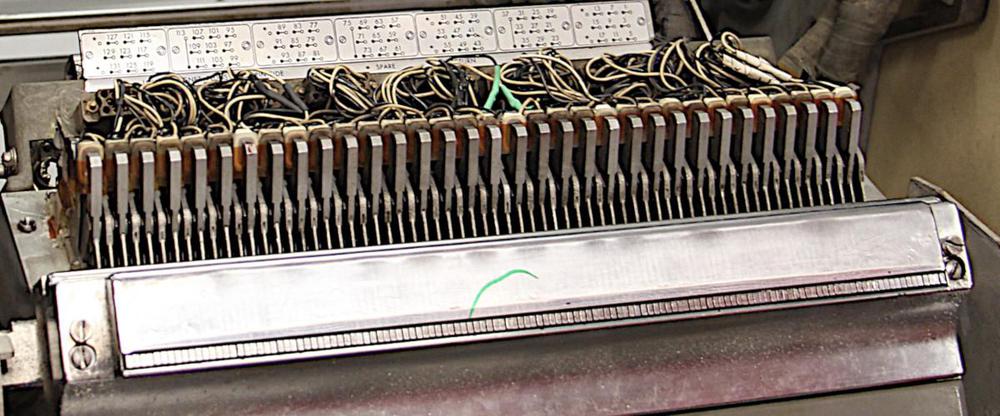
A hammer bank in the IBM 1403 printer. At the bottom, the impact points for the 132 hammers (one for each column) are visible. The coils and wiring for 1/4 (33) of the 132 hammers are visible at the top.

A hammer bank in the IBM 1403 printer. At the bottom, the impact points for the 132 hammers (one for each column) are visible. The coils and wiring for 1/4 (33) of the 132 hammers are visible at the top.

The photo below is a closeup of a hammer. The electromagnet coil and wires are on the upper left. We had to replace this hammer after the coil overheated and smoked; you can see a blackened region on the coil. (This problem happened a while ago due to a bad circuit board, and is unrelated to the printer music.)

An individual hammer from the IBM 1403 printer.

An individual hammer from the IBM 1403 printer.

Generating music

Now that you see how the printer works, with a hammer potentially firing every 11.1 µs, the strategy to make music should be clearer. By printing carefully-selected text, you can control the times at which hammers fire. By firing hammers at specific intervals, you can create a desired frequency. An A note (440 Hz), for instance, can be produced by printing a line of text that fires the hammers every 1/440th of a second. This can be done by printing a 1 in column 1 (the first hammer to be aligned), followed by a # in column 14 on the next scan, a comma in column 30 the scan after that, and so forth. (There's no real pattern to this; it's just how things line up.3) The full line printed to generate this note is below.7 (It may be a bit surprising that with a character set of just 48 characters, the printer includes unusual characters such as ⌑ and ‡.)

1    ⌑Y     C#    0   Q     3,    ‡F      R T   4 -   ,   I     U     $7        M   V .   *        9N     ⌑        ZE     @     P3

The diagram below shows the timing of the hammers, illustrating the uniform 440 Hz frequency produced by the above print line. The diagram has time on the X-axis, with a red bar when each character is printed. The red bars are spaced evenly with a spacing of 1/440th of a second, generating a 440 Hz note. Each bar is labeled with the associated character and column on the page. Note that characters are printed in a different order from how they appear on the line. There's no simple relationship between the arrangement of characters on the line and their time sequence. There are a few gray lines where you'd expect a hammer to fire, but no character is printed. These correspond to times when the chain is syncing up and can't print.

Timing diagram for the note A4. Each red line indicates a printed character.

Timing diagram for the note A4. Each red line indicates a printed character.

By printing a different line, a different note can be produced. Below is the note B5, which is 987 Hz (over an octave higher). As you'd expect, the higher-frequency note has more characters.

1 @EQ4S J   8. N D ‡  S H 7 AM  Y#2   G-  KV . 0 D  Q S J 7&   N D ‡/4  H   AMX0  2 Q G J   W. 0 DP‡  S   7&AM     ‡/4G   *  MX0 D 3

Timing diagram for the note B5. Each red line indicates a printed character.

Timing diagram for the note B5. Each red line indicates a printed character.

The printed line for the low note C♯3 (138 Hz) is below. I was puzzled at first why this line (and the other C♯ notes) had all the characters clustered together, rather than scattered across the line like other notes. It turns out that 138 Hz just happens to correspond to hammers that are consecutive on the line. Even though the characters are clumped together on the line, they are spread out uniformly in time.

16#UZKP*E&38                                                                                                                      

Timing diagram for the note C♯3.

Timing diagram for the note C♯3.

Why chain music might be risky

We were concerned that the print chain music program might damage the printer. There are plenty of stories of people destroying line printers by printing a line that fires all the hammers at once. I think these are mostly urban legends (among other things, the hammers on the 1403 fire one at a time, not all at once). Nonetheless, we were somewhat concerned about chain music overstressing the print chain and breaking it. The photo below shows a print chain that broke during normal use; you can see the broken wires and the individual type slugs.

A broken 1403 print chain. It broke during normal use, not from line printer music. (Photo from TechWorks.)

A broken 1403 print chain. It broke during normal use, not from line printer music. (Photo from TechWorks.)

Print chain were manufactured by winding a thin wire into a band, with type blocks attached. Up until recently, print chains were rare and irreplaceable; if the wire broke, there was no way to fix it. However, the Techworks! museum in Binghamton, NY recently developed a technique to rebuild print chains. Because of this, Frank King (our IBM 1401 guru) approved the use of a chain for line printer music, with some trepidation. Fortunately, the chain survived the music generation just fine. (After studying the music program carefully, I think it puts less stress on the chain than the average program, unless there's some really unfortunate resonance.)

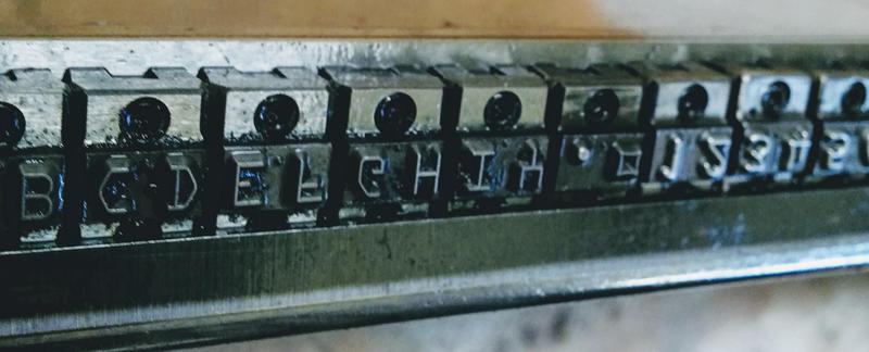
Closeup of the type chain (upside down) for an IBM 1403 line printer.

Closeup of the type chain (upside down) for an IBM 1403 line printer.

The program

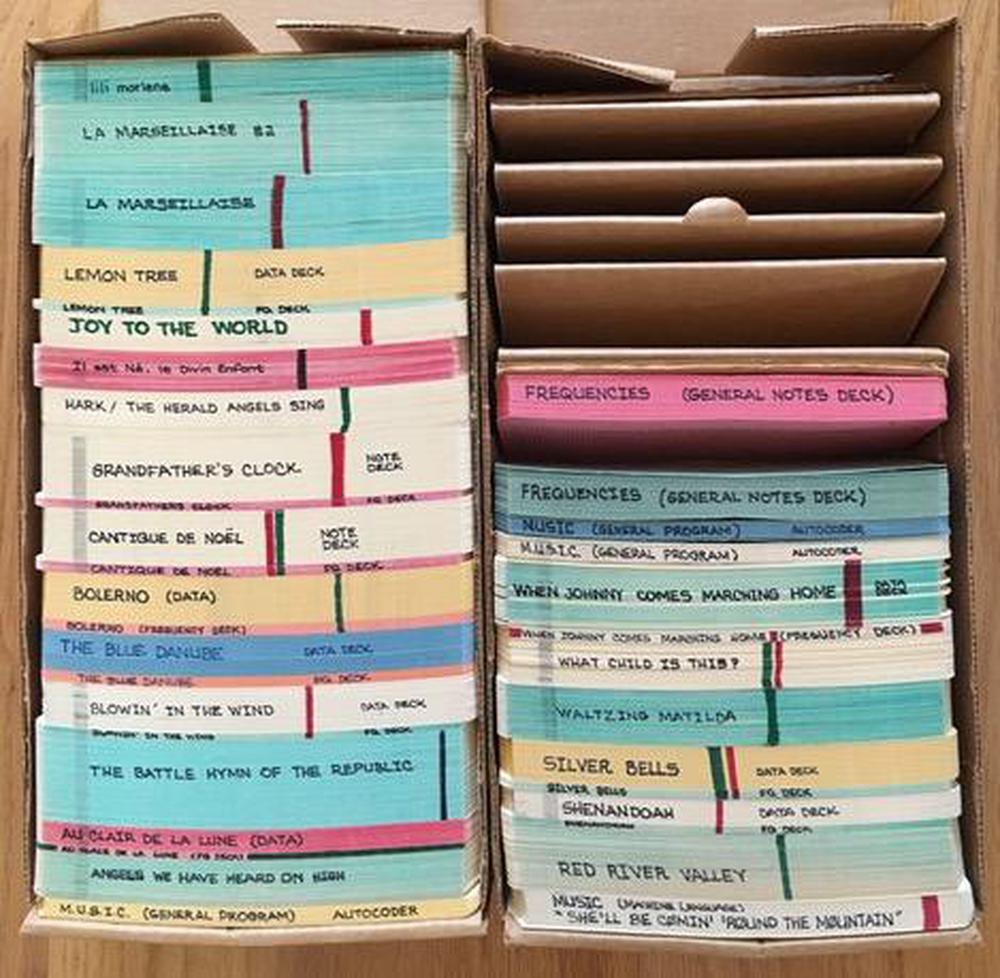
Card decks to play a variety of songs, courtesy of Ron Mak.

Card decks to play a variety of songs, courtesy of Ron Mak.

The source code to the program is long gone, so I disassembled the machine code on the cards to determine how the program works (listing here). First, it reads "frequency cards" that define what line to print for each note. It builds up an array of print lines in memory, along with a table of note names and addresses of the print lines. Next, the program reads the notes of the song, one note per card. (As you can see above, some songs require many cards.) For each note, it looks up the appropriate print line in the note table. Based on the note's duration, it prints the line the appropriate number of times (using a jump table, not a loop). A rest is implemented by looping 200 to 2000 times to provide silence for the appropriate delay.

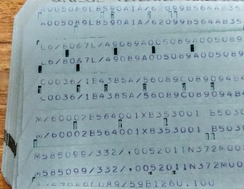
A closeup of cards with the machine code for the music program. For some reason, the contents of each card are printed twice on the card.

A closeup of cards with the machine code for the music program. For some reason, the contents of each card are printed twice on the card.

Machine code for the 1401 is very different from modern machines. One difference is that self-modifying code was very common, while nowadays it is usually frowned upon. For instance, the table of print lines is created by actually modifying load instructions, replacing the address field in the instruction. Even subroutine returns use self-modifying code, putting the return address into a jump instruction at the end of the subroutine. To handle a note, the program generated on-the-fly a sequence of three instructions to load the print line, jump to the print code, and then jump back to the main loop. Self-modifying code made it more challenging for me to understand the program since the disassembled code isn't what actually gets run.

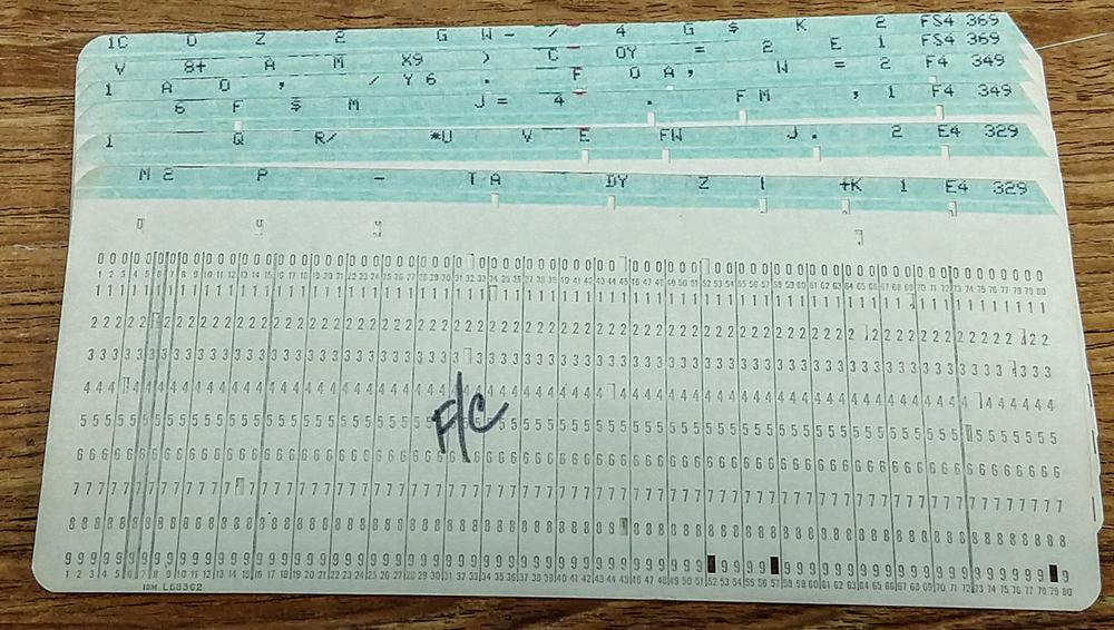
The program cards are followed by frequency cards, defining the print line for each note. The code supported up to 20 different notes, so the frequency cards were selected according to the song's need. Each 132-column line is split across two cards, with the first card defining the right half of the line. Each card is punched at the right with the note name and frequency.

Frequency cards. Each pair of cards defines the 132-character print line that generates the specified note. At the right, the card is punched with the note name (e.g. E4) and frequency (e.g. 329 Hz). The notation F/C labels the first card in the deck.

Frequency cards. Each pair of cards defines the 132-character print line that generates the specified note. At the right, the card is punched with the note name (e.g. E4) and frequency (e.g. 329 Hz). The notation F/C labels the first card in the deck.

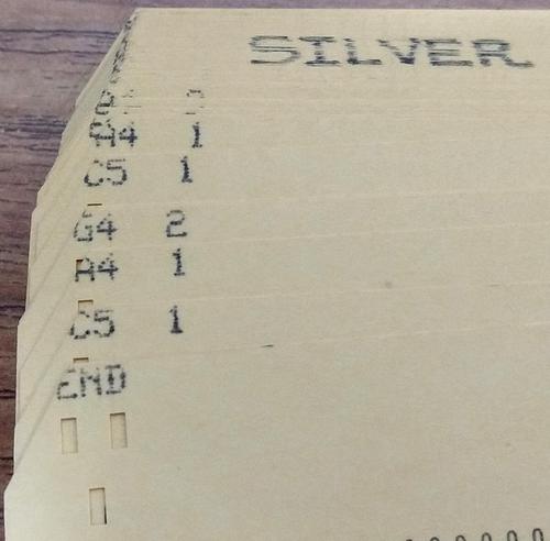
The final set of cards creates the tune, with one card per note (or rest). Each card is punched with a note and duration. A long song may use hundreds of cards. It is straightforward to create a new song, just a matter of punching the tune onto cards. The notes are specified in Standard Pitch Notation with the note name followed by an octave number. For example, C4 is middle C. Since only some print chains had the # symbol, sharps were indicated with an "S", e.g. CS for C♯.

Closeup of the cards for the song Silver Bells. Each card has the note and octave, followed by its duration. The first card is (confusingly) "END", indicating the end of the frequency cards.

Closeup of the cards for the song Silver Bells. Each card has the note and octave, followed by its duration. The first card is (confusingly) "END", indicating the end of the frequency cards.

Conclusion

We succeeded in generating music on the IBM 1403 printer, running programs that hadn't been run in almost 50 years. Although the music quality isn't very good, we were happy that the printer didn't self-destruct. Ron Mak last ran these programs in 1970; this link has some songs from then, such as Raindrops keep fallin' on my head. The video below shows an excerpt of La Marseillaise; in this video you can see each line being printed.

I announce my latest blog posts on Twitter, so follow me at @kenshirriff for future articles. I also have an RSS feed. The Computer History Museum in Mountain View runs demonstrations of the IBM 1401 on Wednesdays and Saturdays so if you're in the area you should definitely check it out (schedule). Thanks to Ron Mak for supplying the vintage programs, Carl Claunch for reading the cards, and the 1401 restoration team for running the program, in particular, Robert Garner and Frank King.

Notes and references

  1. In case you're wondering why nothing shows up on the printer in the video, the printer's line feed was disabled to save paper. You can see the lines being printed in the video at the end of the article. 

  2. Programmers also used the 1401 to generate music on an AM radio via RF interference. Running the right instruction sequence generated a particular tone. We hope to try this in the future. 

  3. I've created an animation of the print chain here that shows exactly how it works; it's more complex than you'd expect. 

  4. The print chain and hammer alignment scheme may seem excessively complicated. But what makes it clever is that the 11.1 µs between hammer times is just enough time to read a character from core memory to see if it matches the chain slug under the hammer, and thus should be printed. In other words, the system is designed to match the mechanical speed of the chain to the electronic speed of core memory. 

  5. The printer's operation is explained in detail in the Field Engineering Manual of Instruction. The section starting on page 37 discusses the chain timing in detail. Each scan is broken down into 3 subscans, but I won't get into that here. Note that while a line is 132 characters, printing a line takes about 150 time intervals (1665 µs); the extra time is used to sync the chain position. (This explains why some notes have "missing" characters in the timing plots.) 

  6. The chain only moves 1/1000 of an inch during the 11.1 µs time., but that is enough to line up the next character and hammer. The trick that makes this work is that the hammer spacing and the chain spacing are very slightly different (a vernier mechanism), so a tiny chain movement causes a much larger change in the alignment position. 

  7. I've archived the code and full set of frequency cards here for future reference. 

Reverse-engineering precision op amps from a 1969 analog computer

$
0
0

We are restoring a vintage1 computer that CuriousMarc recently obtained. Analog computers were formerly popular for fast scientific computation, but pretty much died out in the 1970s. They are interesting, though, as a completely different computing paradigm from digital computers. In this blog post, I'm going to focus on the op amps used in Marc's analog computer, a Simulators Inc. model 240.

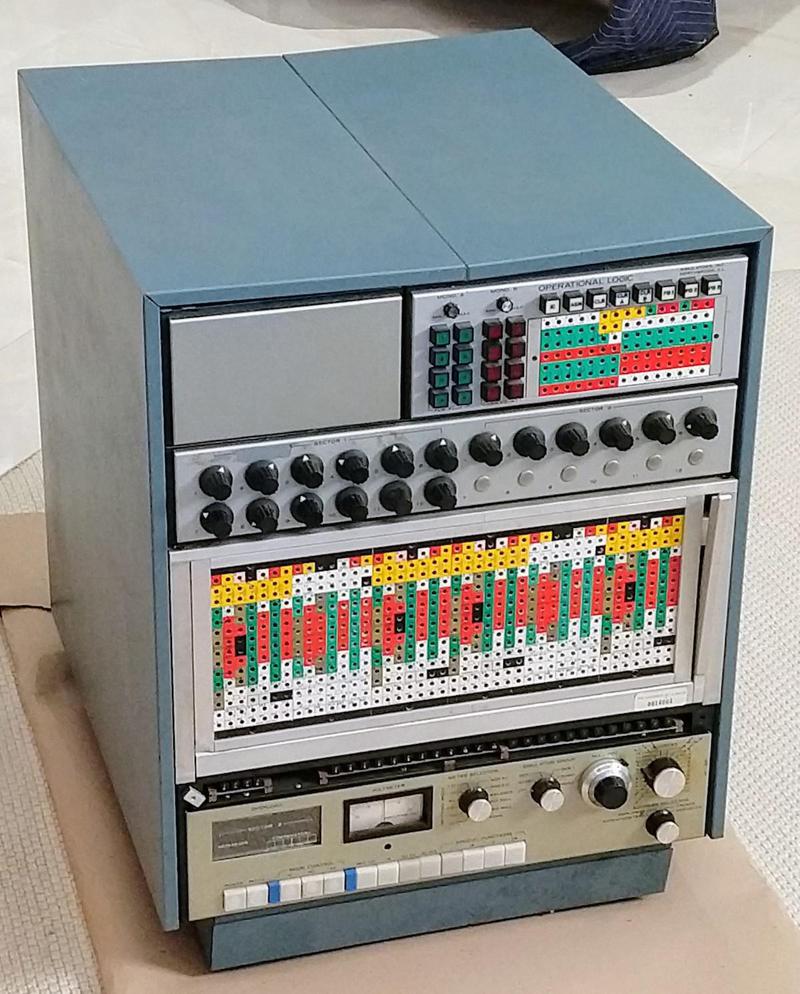
The Model 240 analog computer from Simulators Inc. was a "precision general purpose analog computer" for the desk top, with up to 24 op amps. (This one has 20 op amps.)

The Model 240 analog computer from Simulators Inc. was a "precision general purpose analog computer" for the desk top, with up to 24 op amps. (This one has 20 op amps.)

What's an analog computer?

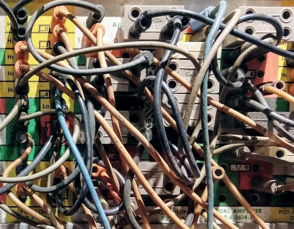
An analog computer performs computations using physical, continuously changeable values such as voltages. This is in contrast to a digital computer that uses discrete binary values. Analog computers have a long history including gear mechanisms, slide rules, wheel-and-disk integrators, tide computers, and mechanical gun targeting systems. The "classic" analog computers of the 1950s and 1960s, however, used op amps and integrators to solve differential equations. They were typically programmed by plugging cables into a patch panel, yielding a spaghetti-like tangle of wires.

An analog computer was "programmed" by plugging wires into the patch panel. This panel is from an EAI analog computer at the Computer History Museum.

An analog computer was "programmed" by plugging wires into the patch panel. This panel is from an EAI analog computer at the Computer History Museum.

The big advantage of analog computers was their speed. They computed results almost instantaneously with their components operating in parallel, while digital computers needed to chug away performing calculations, often for a long time. This made analog computers especially useful for real-time simulations. A disadvantage of analog computers is they were only as accurate as their components; if you wanted 4 digits of accuracy, you needed expensive 0.01% accurate resistors. (In contrast, digital computers can be made as accurate as desired simply by using more bits of precision.) Unfortunately for analog computers, digital computers became exponentially faster and more powerful, so by the 1970s there was little reason to use analog computers.

Inside the analog computer

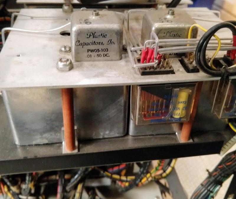
The heart of the analog computer was its operational amplifiers or op amps. Op amps could sum and scale their inputs, providing basic mathematics. But more importantly, integrators were constructed by combining an op amp with a precision capacitor (below). An integrator computed the integral of its input over time by charging the capacitor. This allowed analog computers to solve differential equations. (It may seem strange that integration, a mathematically sophisticated operation, was a basic building block of analog computers, but that's the way the hardware worked out.)

The integrators in the analog computer used large precision capacitors. The adjustable capacitor on top is 10 nanofarads, while the large metal box below is an adjustable 10 microfarad capacitor. These capacitors were designed for very low leakage so the integrated value wouldn't leak away. In front are relays to select the capacitors.

The integrators in the analog computer used large precision capacitors. The adjustable capacitor on top is 10 nanofarads, while the large metal box below is an adjustable 10 microfarad capacitor. These capacitors were designed for very low leakage so the integrated value wouldn't leak away. In front are relays to select the capacitors.

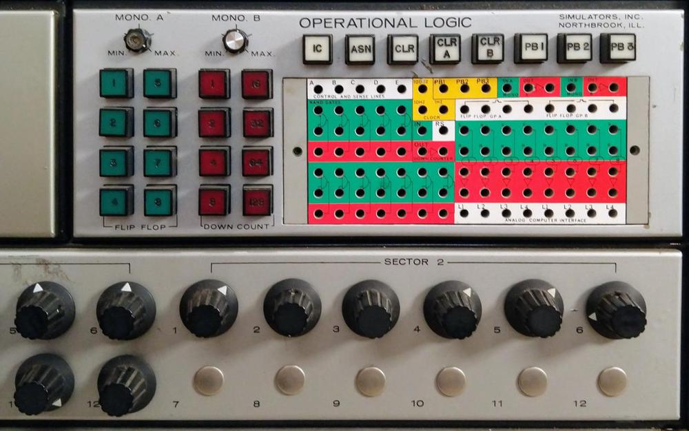
Analog computers used multiple potentiometers (below) to set input values and scaling constants. These potentiometers rotated through 10 turns to provide high accuracy. A voltmeter was used to check the potentiometer values. The voltmeter could also be used to display output values, but more often, outputs were displayed on an oscilloscope, strip chart, or X-Y plotter.

At top, the digital section of the analog computer. The potentiometers are below; some were not installed in this model of the computer. The blank panel in the upper left could hold a digital voltmeter.

At top, the digital section of the analog computer. The potentiometers are below; some were not installed in this model of the computer. The blank panel in the upper left could hold a digital voltmeter.

Some analog computers included digital components such as gates, flip flops, one-shots, and counters. This functionality supported more complex techniques, such as iterating through a solution space. Marc's computer has some digital logic, accessed through the colorful patch panel shown above.

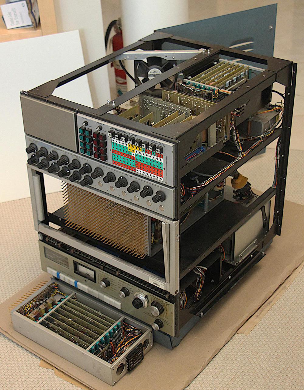
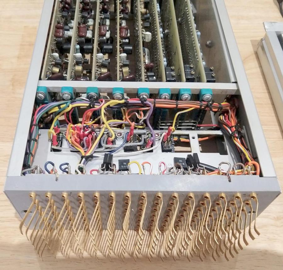
The photo below shows the computer partially disassembled. The computer is more complex inside than I expected, with many circuit boards. The patch panel has been removed, revealing the grid of contacts behind it. When a cable is plugged into the patch panel, the cable connects to these contacts, wiring up the program. The computer has five modules behind the patch panel; the leftmost module has been removed and is sitting in front of the computer.2 The boards visible at the top of the computer support the digital logic and two analog multipliers. The power supply and circuitry for the front panel are at the bottom.

The analog computer with the sides removed to show the internal circuitry. One module has been removed and placed in front of the computer.

The analog computer with the sides removed to show the internal circuitry. One module has been removed and placed in front of the computer.

A closeup of a module is shown below, with the patch panel contacts in front. The module's eight circuit boards can be seen at the back. From left to right, the boards are four op amps (4 boards), miscellaneous circuitry (1 board), and a multiplier (3 boards). Multiplication was surprisingly difficult to implement in an analog computer; the three boards implement a single circuit to multiply two values.3

One of the modules. The "fingers" on front contact plugs inserted into the patch panel. Square high-precision (0.01%) resistors are visible behind the fingers.

One of the modules. The "fingers" on front contact plugs inserted into the patch panel. Square high-precision (0.01%) resistors are visible behind the fingers.

The op amps

In the above photo, each op amp took up a full board of components. Each board includes an op amp integrated circuit, which raises the question of why so many other components are required. The reason is that analog computers placed heavy demands on op amp performance. In particular, the op amps need to work with signals at DC and at low frequencies, and op amps inconveniently perform poorly in this range, operating better at higher frequencies.

In 1949, a solution to op amp problems at low frequencies was developed: the chopper op amp.4 The idea is that a chopper modulates the input at, say 400 Hz. The op amp happily amplifies this 400-Hz AC signal. A second chopper demodulates the AC output back to DC5, providing much better performance than directly amplifying the DC signal.4 The op amp boards in the analog computer add a chopper circuit to the IC op amp to improve its performance.6

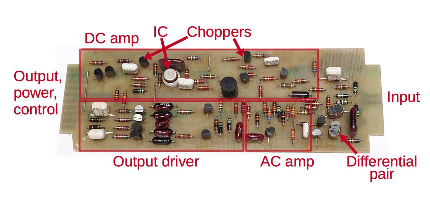
The diagram below shows one of the op amp boards.8 The op amp's single input7 is on the right (separated from all the other connections on the left, to avoid noise). The input is split into three paths. The first path is to the DC chopper amplifier. The signal goes through a low-pass filter (i.e. resistor and capacitor) to extract the DC and low-frequency signal. The chopper itself is pretty simple: a JFET transistor alternately grounds the signal as driven by an external 400 Hz oscillator. This modulated 400 Hz signal is fed to the op amp IC, an Amelco 809 high-performance op amp, introduced in 1967.9 The IC is in a round metal can; this packaging was common back then and helped shield the op amp from noise. Finally, the IC's output goes through a second chopper and filter to demodulate it.

An op amp board from the analog computer with functional groups labeled. Even though the board uses an integrated circuit op amp, many additional circuits are necessary to obtain the performance required.

An op amp board from the analog computer with functional groups labeled. Even though the board uses an integrated circuit op amp, many additional circuits are necessary to obtain the performance required.

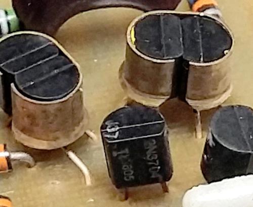
Next, the second input path is combined with the DC amplifier's output. Most op amps are based around a differential pair, and this board is no exception. In a differential pair, two transistors provide high-gain amplification of the difference between two input signals. This differential pair's inputs are the board's input and the signal from the DC chopper amp so it amplifies both the original input and the DC signal. The two transistors in the differential pair need to be exactly balanced for the op amp to function accurately. In particular, the two transistors need to be kept at the same temperature, so they are fastened together with a metal clip (below).

Critical transistors are held together with metal clips to ensure they stay at the same temperature. The differential pair is on the right, while the transistors on the left buffer the inputs.

Critical transistors are held together with metal clips to ensure they stay at the same temperature. The differential pair is on the right, while the transistors on the left buffer the inputs.

The third input path goes to the AC amplifier. The input goes through a high-pass filter (resistor and capacitor) and then a simple transistor buffer. This "feedforward" signal is combined with the output from the differential pair to improve the amplifier's frequency response. At this point, the input has been amplified three different ways to yield good low-frequency and high-frequency performance.

The final stage of the op amp board is an output amplifier to provide high-current output for use by the rest of the computer. This amplifier is implemented with a Class AB amplifier circuit. Individual transistors at the time weren't sufficiently powerful, so it uses two NPN transistors and two PNP transistors to drive the output.

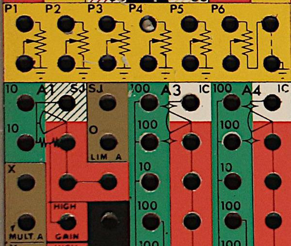
Each op amp board has its input and output wired to the patch panel. On the patch panel below, the op amps (A1 through A4) are shaped like pieces of pie; their inputs are green and outputs are red. The op amps used for integrators are also wired to the integration capacitors.

Detail of the patch panel showing the connections for op amps A1, A3, and A4. The inputs are green and the outputs are red. Initial conditions (IC) are in white. The potentiometer connections are above (yellow).

Detail of the patch panel showing the connections for op amps A1, A3, and A4. The inputs are green and the outputs are red. Initial conditions (IC) are in white. The potentiometer connections are above (yellow).

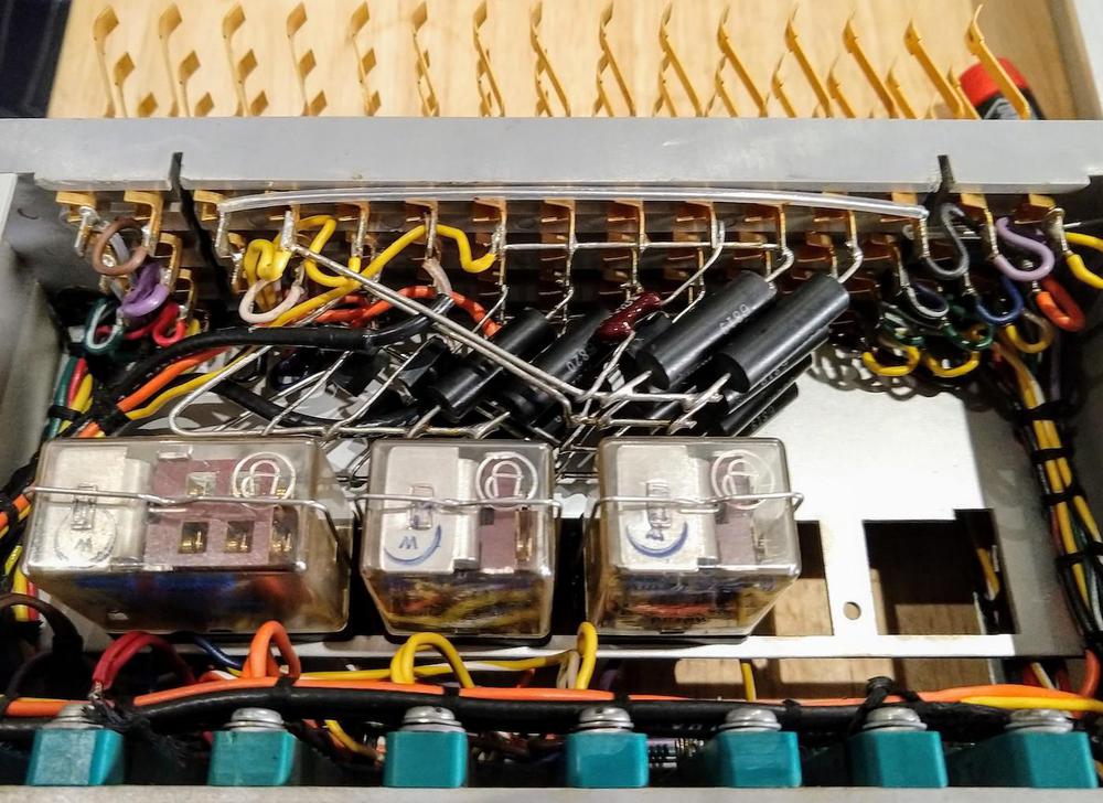
On the patch panel, each op amp has multiple input plugs with different resistor values for scaling; these are the "10" and "100" numbers above. The photo below shows these high-precision resistors (black cylinders) attached directly to the patch panel contacts. Integrator inputs are controlled by relays (below) and electronic switches so the analog computer can initialize the integration capacitors, run the computation, and then hold the result for analysis.

Resistors (black cylinders) are attached directly to the patch panel contacts. The relays in the middle control the computer's different states: initial constants, operate, and hold. The circuit boards plug into the green connectors at the bottom.

Resistors (black cylinders) are attached directly to the patch panel contacts. The relays in the middle control the computer's different states: initial constants, operate, and hold. The circuit boards plug into the green connectors at the bottom.

Conclusion

Even though op amp integrated circuits existed in the late 1960s, their performance wasn't good enough for analog computers. Instead, a whole board of components was used for a single op amp, combining the IC op amp with a chopper and other circuitry to yield a high-precision op amp. Although improvements in integrated circuits led to exponential increases in digital computer performance, analog computers received much smaller benefits from ICs. As a result, digital computers almost entirely took over and analog computers are now historical artifacts.

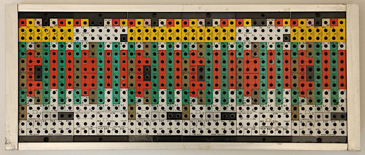
The removable patch panel for the analog computer. The computer was programmed by plugging wires into the holes. 
The panel is removable, so one programmer could use the analog computer while another is wiring up a panel.
(Click to enlarge.)

The removable patch panel for the analog computer. The computer was programmed by plugging wires into the holes. The panel is removable, so one programmer could use the analog computer while another is wiring up a panel. (Click to enlarge.)

You might wonder why I'm studying the circuitry of this analog computer in such detail. The reason is that we're trying to restore the computer, but we don't have documentation.1011 Thus, I'm reverse-engineering it to determine how to restore it to operating condition and how to program it. While the circuit boards are not too complex, the computer contains many different boards to analyze. The hardest part is figuring out the connectivity of the many tightly-bundled wiring harnesses, mostly by brute-force beeping out connections with a multimeter.

You can expect more analog computer posts as we continue the restoration. Follow me on Twitter @kenshirriff to stay informed of future articles. I also have an RSS feed.

Notes and references

  1. The computer's integrated circuits have 1968 and 1969 date codes on them, so I think the computer was manufactured in 1969. 

  2. When fully populated, the computer has 6 modules behind the patch panel, but the one on the right is missing. At first, we thought the module had been lost at some point, but it appears that this computer was a lower-cost model and was never fully populated. Evidence of this is that 1/4 of the potentiometers above the patch panel are not installed; these potentiometers would be handled by the missing module. 

  3. Analog computers could implement arbitrary functions using diode-resistor networks. (Each diode turned on at a particular input voltage level, and contributed a ramp to the output.) For multiplication, diode-resistor networks were configured to implement a parabolic function (i.e. squaring). Multiplication was implemented through the identity X×Y = ((X+Y)2 - (X-Y)2)/4. The sum and difference were computed using op amps, while squaring was done with the parabolic function generator. 

  4. Modern chopper op amps use a more complex chopper-stabilizing mechanism, with two op amps. A secondary op amp uses the chopped signal to null out the main op amp. This tutorial discusses the difference between the classic and modern chopper op amps; there's also a discussion here. The point of this footnote is to avoid confusion between the design of chopper op amps used in the analog computer and modern chopper designs. 

  5. You can sort of think of the chopper as performing amplitude modulation on the signal, like an AM radio signal. However, the demodulation needs to be "phase-sensitive" so it can tell the difference between a positive input and a negative input. This is in contrast to AM-radio demodulation, which can be done with a diode since phase doesn't matter. 

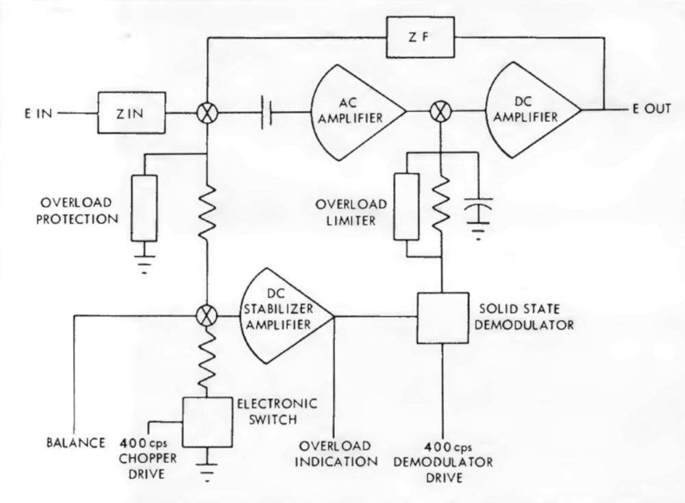
  6. The diagram below (from the brochure) shows the structure of the op amp board. The basic idea is that part of the input goes through a capacitor (i.e. high-pass filter) into the AC amplifier. The input also goes into the "DC stabilizer amplifier", which has a chopper on its input. The output is demodulated and put through a low-pass filter (resistor/capacitor). The two amplifier outputs are combined and fed into the "DC amplifier", the output amplifier.

    Simplified schematic of the op amp.

    Simplified schematic of the op amp.

    Note the circuitry for overload detection and protection. In an analog computer, overload can easily happen if any of the values get higher than expected and exceed the op amp limits (+/- 10 volts). This is bad because it will cause the results to be wrong. The op amp detects overload and illuminates a panel light so the user knows there is a problem. An important part of analog computer programming is how to scale everything so the mathematical values fit within the physical limits of the system. 

  7. Nowadays, op amps have a positive and negative input. In analog computers, however, op amps usually had just the negative input. Thus, they summed and inverted their inputs. 

  8. For reference, I've reverse-engineered the pinout of the op amp board. The input is two shorted pins on the right. The pins along the left of the board (with their connector label) are:
    L: balance in
    K: chopper ground
    J: overload signal out
    H: chopper drive in
    F: ground
    E: ground
    D: -15V
    C: +15V
    B: op amp output
    A: unused 

  9. Although now almost forgotten, Amelco was an important semiconductor company producing high-performance op amps. Among other things, Amelco made the first JFET op amp. It was founded by Hoerni (who invented the "planar process" for ICs at Fairchild). I reverse-engineered a hybrid Amelco op amp and discuss the history of Amelco in this article. The Amelco 809C op amp datasheet can be found here

  10. As far as documentation on this computer, archive.org has a Simulators Inc 240 brochure scanned from "Ted Nelson's Junk Mail". The Analog Computer Museum has a brochure in German for the Dornier 240, an almost identical computer. (I haven't been able to find out the relationship between Simulators Inc and Dornier, but presumably one company licensed it from the other.) 

  11. If you're looking for books on analog computers, here are my comments on ones I've read recently:
    Analog computer programming is a modern book on analog computers, and a good place to start.
    Introduction to analog computer programming is a reasonable introduction; the PDF is online.
    Analog and analog/hybrid computer programming comprehensively explains how to solve many different types of problems.
    Electronic analog and hybrid computers has a detailed discussion of the hardware implementations of analog computers of this era.
    Analog and hybrid computing provides a basic description of analog computers and their programming.
    Analog computer techniques is hard to follow and from the vacuum tube era, so I don't recommend it. 

A computer built from NOR gates: inside the Apollo Guidance Computer

$
0
0

We recently restored an Apollo Guidance Computer1, the computer that provided guidance, navigation, and control onboard the Apollo flights to the Moon. This historic computer was one of the first to use integrated circuits and its CPU was built entirely from NOR gates.2 In this blog post, I describe the architecture and circuitry of the CPU.

Architecture of the Apollo Guidance Computer

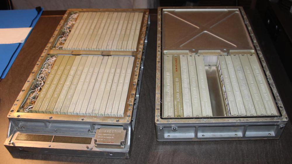
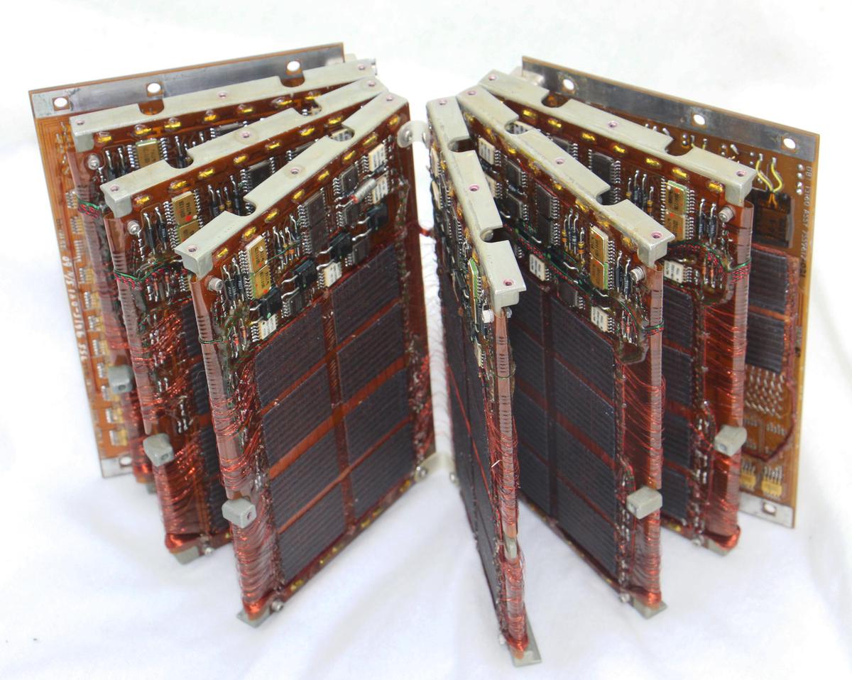
The Apollo Guidance Computer with the two trays separated. The tray on the left holds the logic circuitry built from NOR gates. The tray on the right holds memory and supporting circuitry.

The Apollo Guidance Computer with the two trays separated. The tray on the left holds the logic circuitry built from NOR gates. The tray on the right holds memory and supporting circuitry.

The Apollo Guidance Computer was developed in the 1960s for the Apollo missions to the Moon. In an era when most computers ranged from refrigerator-sized to room-sized, the Apollo Guidance Computer was unusual—small enough to fit onboard the Apollo spacecraft, weighing 70 pounds and under a cubic foot in size.

The AGC is a 15-bit computer. It may seem bizarre to have a word size that isn't a power of two, but in the 1960s before bytes became popular, computers used a wide variety of word sizes. In the case of the AGC, 15 bits provided sufficient accuracy to land on the moon (using double- and triple-precision values as needed), so 16 bits would have increased the size and weight of the computer unnecessarily.4

The Apollo Guidance Computer has a fairly basic architecture, even by 1960s standards. Although it was built in the era of complex, powerful mainframes, the Apollo Guidance Computer had limited performance; it is more similar to an early microprocessor in power and architecture.3 The AGC's strengths were its compact size and extensive real-time I/O capability. (I'll discuss I/O in another article.)5

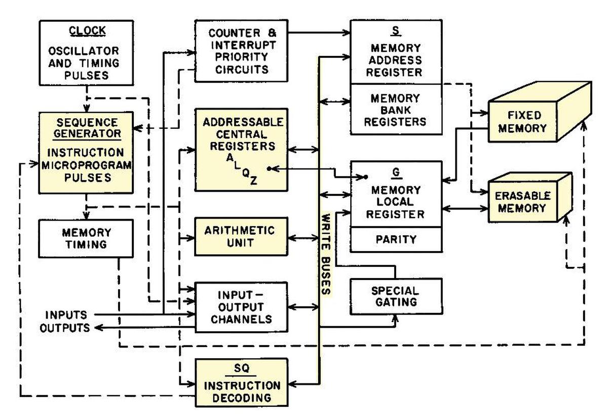
The architecture diagram below shows the main components of the AGC. The parts I'll focus on are highlighted. The AGC has a small set of registers, along with a simple arithmetic unit that only does addition. It has just 36K words of ROM (fixed memory) and 2K words of RAM (erasable memory). The "write bus" was the main communication path between the components. Instruction decoding and the sequence generator produced the control pulses that directed the AGC.

Block diagram of the Apollo Guidance Computer. From Space Navigation Guidance and Control, R-500, VI-14.

Block diagram of the Apollo Guidance Computer. From Space Navigation Guidance and Control, R-500, VI-14.

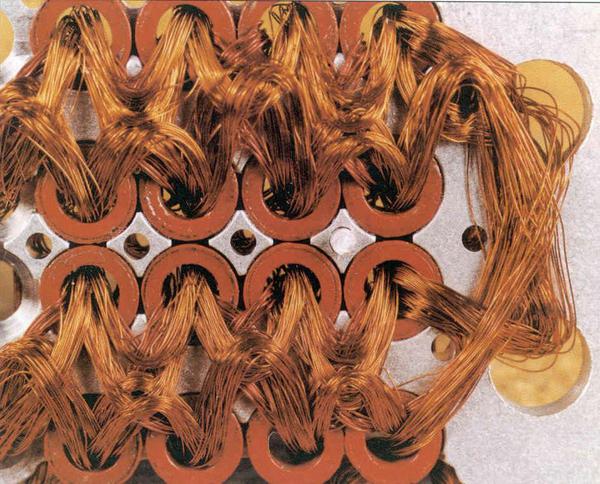
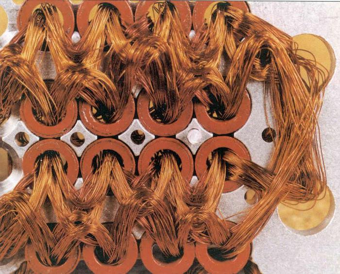
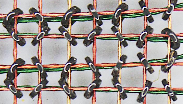
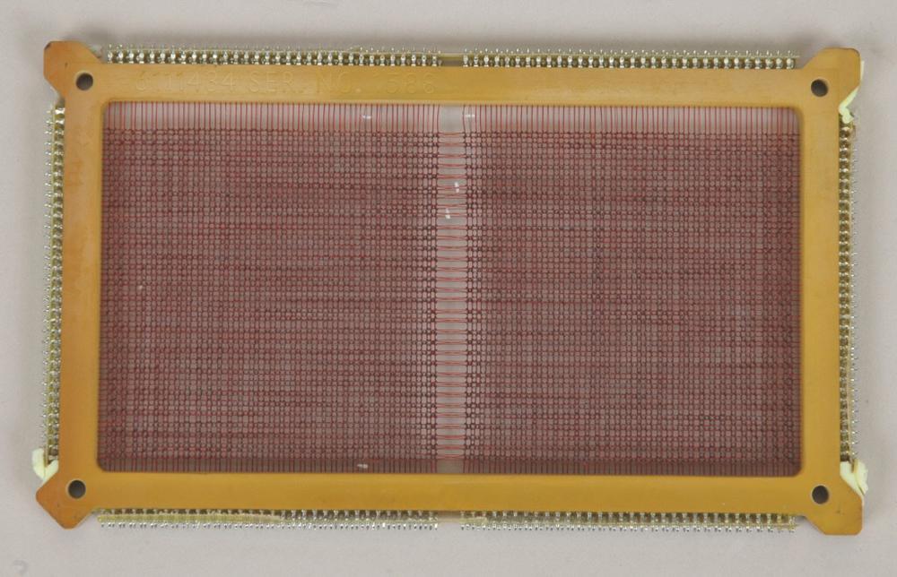
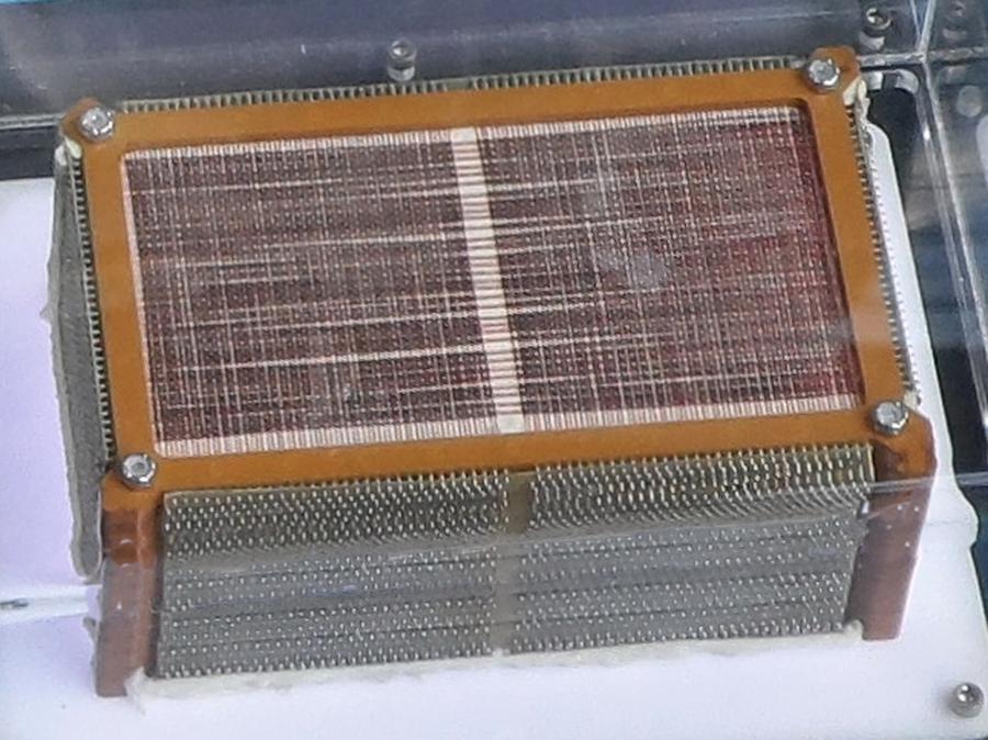
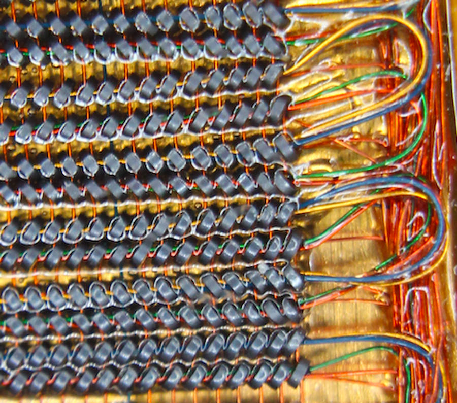
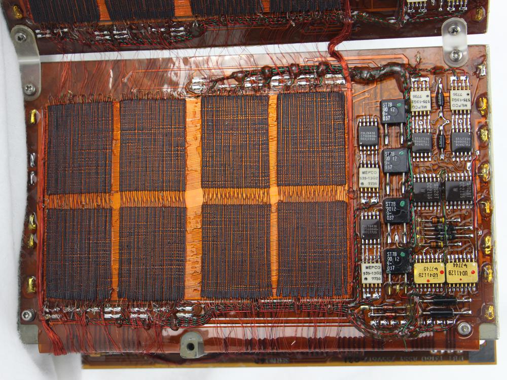
About half of the architecture diagram is taken up by memory, reflecting that in many ways the architecture of the Apollo Guidance Computer was designed around its memory. Like most computers of the 1960s, the AGC used core memory, storing each bit in a tiny ferrite ring (core) threaded onto a grid of wires. (Because a separate physical core was required for every bit, core memory capacity was drastically smaller than modern semiconductor memory.) A property of core memory was that reading a word from memory erased that word, so a value had to be written back to memory after each access. The AGC also had fixed (ROM), the famous core ropes used for program storage where bits were physically woven into the wiring pattern (below). (I've written about the AGC's core memory and core rope memory in detail.)

Detail of core rope memory wiring from an early (Block I) Apollo Guidance Computer. Photo from Raytheon.

Detail of core rope memory wiring from an early (Block I) Apollo Guidance Computer. Photo from Raytheon.

NOR gates

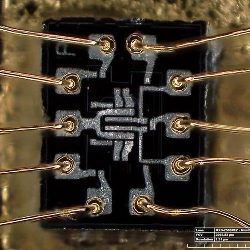
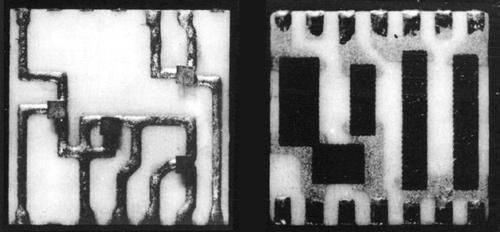
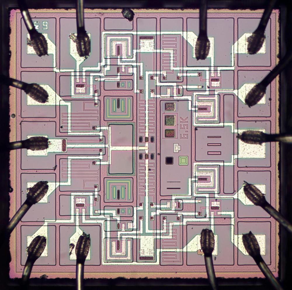
The Apollo Guidance Computer was one of the very first computers to use integrated circuits. These early ICs were very limited; the AGC's chips (below)2 contained just six transistors and eight resistors, implementing two 3-input NOR gates.

Die photo of the dual 3-input NOR gate used in the AGC. The ten bond wires around the outside of the die connect to the IC's external pins. Photo by Lisa Young, Smithsonian.

Die photo of the dual 3-input NOR gate used in the AGC. The ten bond wires around the outside of the die connect to the IC's external pins. Photo by Lisa Young, Smithsonian.

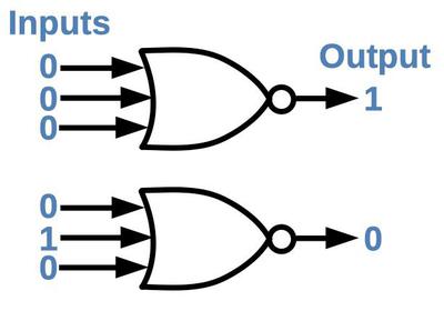
The symbol for a NOR gate is shown below. It is a very simple logic gate: if all inputs are low, the output is high. It might be surprising that NOR gates are sufficient to build a computer, but NOR is a universal gate: you can make any other logic gate out of NOR gates. For instance, wiring the inputs of a NOR gate together forms an inverter. Putting an inverter on the output of a NOR gate produces an OR gate. Putting inverters on the inputs of a NOR gate produces an AND gate.6 More complex circuits, such as flip flops, adders, and counters can be built from these gates.

The NOR gate generates a 1 output if all inputs are 0. If any input is a 1 (or multiple inputs), the NOR gate generates a 0 output.

The NOR gate generates a 1 output if all inputs are 0. If any input is a 1 (or multiple inputs), the NOR gate generates a 0 output.

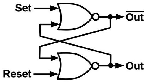
One building block that appears frequently in the AGC is the set-reset latch. This simple circuit is built from two NOR gates and stores one bit of data: the set input stores a 1 bit and the reset input stores a 0 bit. In more detail, a 1 pulse on the set input turns the top NOR gate off and the bottom one on, so the output is a 1. A 1 pulse on the reset input does the opposite so the output is a 0. If both inputs are 0, the latch remembers its previous state, providing storage. The next section will show how the latch circuit is used to build registers.

A set-reset latch built from two NOR gates. If one NOR gate is on, it forces the other one off. The overbar on the top output indicates that it is the complement of the lower output.

A set-reset latch built from two NOR gates. If one NOR gate is on, it forces the other one off. The overbar on the top output indicates that it is the complement of the lower output.

The registers

The Apollo Guidance Computer has a small set of registers to store values temporarily outside of core memory. The main register is the accumulator (A), which is used in many arithmetic operations. The AGC also has a program counter register (Z), arithmetic unit registers (X and Y), a buffer register (B), return address register (Q)7, and a few others. For memory accesses, the AGC has a memory address register (S) and a memory buffer register (G) for data. The AGC also has some registers that reside in core memory, such as I/O counters.

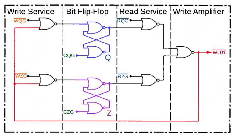
The following diagram outlines the register circuitry for the AGC, simplified to a single bit and two registers (Q and Z). Each register bit has a latch (flip-flop), using the circuit described earlier (blue and purple). Data is transmitted both to and from the registers on the write bus (red). To write to a register, the latch is first reset by a clear signal (CQG or CZG, green). A "write service" gate signal (WQG or WZG, orange) then allows the data on the write bus to set the corresponding register latch. To read a register, a "read service" gate signal (RQG or RZG, cyan) passes the latch's output through the write amplifier to the write bus, for use by other parts of the AGC. The complete register circuitry is more complex, with multiple 16-bit registers, but follows this basic structure.

Simplified diagram of AGC register structure, showing one bit of the Q and Z registers. (Source)

Simplified diagram of AGC register structure, showing one bit of the Q and Z registers. (Source)

The register diagram illustrates three key points. First, the register circuitry is built from NOR gates. Second, data movement through the AGC centers on the write bus. Finally, the register actions (like other AGC actions) depend on specific control signals at the right time; the "control" section of this post will discuss how these signals are generated.

The arithmetic unit

Most computers have an arithmetic logic unit (ALU) that performs arithmetic and Boolean logic operations. Compared to most computers, the AGC's arithmetic unit is very limited: the only operation it performs is addition of 16-bit values, so it's called an arithmetic unit, not an arithmetic logic unit. (Despite its limited arithmetic unit, the AGC can perform a variety of arithmetic and logic operations including multiplication and division, as explained in the footnote.9)

The schematic below shows one bit of the AGC's arithmetic unit. The full adder (red) computes the sum of two bits and a carry. In particular, the adder sums the X bit, Y bit, and carry-in, generating the sum bit (sent to the write bus) and carry bit. The carry is passed to the next adder, allowing adders to be combined to add longer words.8)

Schematic of one bit in the AGC's arithmetic unit. (Based on AGC handbook p214.)

Schematic of one bit in the AGC's arithmetic unit. (Based on AGC handbook p214.)

The X register and Y register (purple and green) provide the two inputs to the adder. These are implemented with the NOR-gate latch circuits described earlier. The circuitry in blue writes a value to the X or Y register as specified by the control signals. This circuitry is fairly complex since it allows constants and shifted values to be stored in the registers, but I won't go into the details. Note the "A2X" control signal that gates the A register value into the X register; it will be important in the following discussion.

The photo below shows the physical implementation of the AGC's circuitry. This module implements four bits of the registers and arithmetic unit. The flat-pack ICs are the black rectangles; each module has two boards with 60 chips each, for a total of 240 NOR gates. The arithmetic unit and registers are built from four identical modules, each handling four bits; this is similar to a bit-slice processor.

The arithmetic unit and registers are implemented in four identical modules. Each module implements 4 bits. The modules are installed in slots A8 through A11 of the AGC.

The arithmetic unit and registers are implemented in four identical modules. Each module implements 4 bits. The modules are installed in slots A8 through A11 of the AGC.

Executing an instruction

This section illustrates the sequence of operations that the AGC performs to execute an instruction. In particular, I'll show how an addition instruction, ADS (add to storage), takes place. This instruction reads a value from memory, adds it to the accumulator (A register), and stores the sum in both the accumulator and memory. This is a single machine instruction, but the AGC performs many steps and many values move back and forth to accomplish it.

Instruction timing is driven by the core memory subsystem. In particular, reading a value from core memory erases the stored value, so a value must be written back after each read. Also, when accessing core memory there is a delay between when the address is set up and when the data is available. The result is that each memory cycle takes 12 time steps to perform first a read and then a write. Each time interval (T1 to T12) takes just under one microsecond, and the full memory cycle takes 11.7µs, called a Memory Cycle Time (MCT).

The erasable core memory module from the Apollo Guidance Computer. This module holds 2 kilowords of memory, with a tiny ferrite core storing each bit. To read memory, high-current pulses flip the magnetization of the cores, erasing the word.

The erasable core memory module from the Apollo Guidance Computer. This module holds 2 kilowords of memory, with a tiny ferrite core storing each bit. To read memory, high-current pulses flip the magnetization of the cores, erasing the word.

The MCT is the basic time unit for instruction execution. A typical instruction requires two memory cycles: one memory access to fetch the instruction from memory, and one memory access to perform the operation.13 Thus, a typical instruction requires two MCTs (23.4µs), yielding about 43,000 instructions per second. (This is extremely slow compared to modern processors performing billions of instructions per second.)

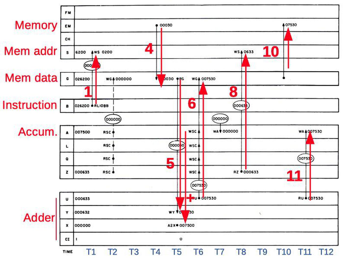
Internally, the Apollo Guidance Computer processes instructions by breaking an instruction into subinstructions, where each subinstruction takes one memory cycle For example, the ADS instruction consists of two subinstructions: the ADS0 subinstruction (which does the addition) and the STD2 subinstruction (which fetches the next instruction, and is common to most instructions). The diagram below shows the data movement inside the AGC to execute the ADS0 subinstruction. The 12 times steps are indicated left to right.

Operations during the ADS0 (add to storage) subinstruction. Arrows show important data movement. Based on the manual.

Operations during the ADS0 (add to storage) subinstruction. Arrows show important data movement. Based on the manual.

The important steps are:
T1: The operand address is copied from the instruction register (B) to the memory address register (S) to start a memory read.
T4: The operand is read from core memory to the memory data register (G).
T5: The operand is copied from (G) to the adder (Y). The accumulator value (A) is copied to the adder (X).
T6: The adder computes the sum (U), which is copied to the memory data register (G).
T8: The program counter (Z) is copied to the memory address register (S) to prepare for fetching the next instruction from core memory.
T10: The sum in the memory data register (G) is written back to core memory.
T11: The sum (U) is copied to the accumulator (A).

Even though this is a simple add instruction, many values are moved around during the 12 time intervals. Each of these actions has a control signal associated with it; for instance, the signal A2X at time T5 causes the accumulator (A) value to be copied to the X register. Copying the G register to the Y register takes two control pulses: RG (read G) and WY (write Y). The next section will explain how the AGC's control unit generates the appropriate control signals for each instruction, focusing on these A2X, RG, and WY control pulses needed by ADS0 at time T5.

The control unit

As in most computers, the AGC's control unit decodes each instruction and generates the control signals that tell the rest of the processor (the datapath) what to do. The AGC uses a hardwired control unit built from NOR gates to generate the control signals. The AGC does not use microcode; there are no microinstructions and the AGC does not have a control store (which would have taken too much physical space).12

The heart of the AGC's control unit is called the crosspoint generator. Conceptually, the crosspoint generator takes the subinstruction and the time step, and generates the control signals for that combination of subinstruction and time step. (You can think of the crosspoint generator as a grid with subinstructions in one direction and time steps in the other, with control signals assigned to each point where the lines cross.) For instance, going back to the ADS0 subinstruction, at time T5 the crosspoint generator would generate the A2X, RG, and WY control pulses, causing the desired data movement.

The crosspoint generator required a lot of circuitry and was split across three modules; this is module A6. Note the added wires to modify the circuitry. This is an earlier module used for ground testing; modules in flight did not have these wires.

The crosspoint generator required a lot of circuitry and was split across three modules; this is module A6. Note the added wires to modify the circuitry. This is an earlier module used for ground testing; modules in flight did not have these wires.

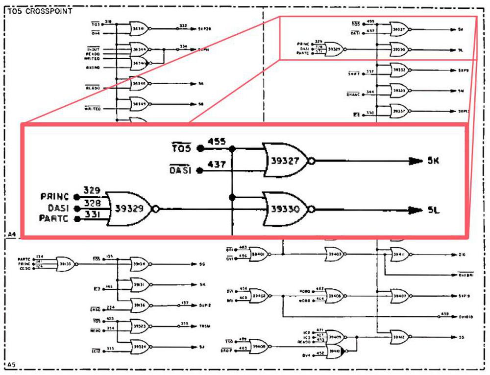
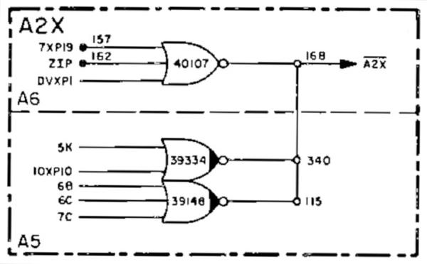
For efficiency, the implementation of the control unit is highly optimized. Instructions with similar behavior are combined and processed together by the crosspoint generator to reduce circuitry. For instance, the AGC has a "Double-precision Add to Storage" instruction (DAS). Since this is roughly similar to performing two single-word adds, the DAS1 subinstruction and ADS0 subinstruction share logic in the crosspoint generator. The schematic below shows the crosspoint generator circuitry for time T5, highlighting the logic for subinstruction ADS0 (using the DAS1 signal). For instance, the 5K signal is generated from the combination of DAS1 and T5.

Crosspoint circuit for signals generated at time T5. With negative inputs, these NOR gates act as AND gates, detecting a particular subinstruction AND T05. From Apollo Lunar Excursion Manual.

Crosspoint circuit for signals generated at time T5. With negative inputs, these NOR gates act as AND gates, detecting a particular subinstruction AND T05. From Apollo Lunar Excursion Manual.

But what are the 5K and 5L signals? These are another optimization. Many control pulses often occur together, so instead of generating all the control pulses directly, the crosspoint generates intermediate crosspoint signals. For instance, 5K generates both the A2X and RG control pulses, while 5L generates the WY control pulse. The diagram below shows how the A2X signal is generated: any of 8 different signals (including 5K) generate A2X.15 Similar circuits generate the other control pulses. These optimizations reduced the size of the crosspoint generator, but it was still large, split across three modules in the AGC.

The A2X control signal is generated from multiple "crosspoint pulses" from the crosspoint generator. The different possibilities are ORed together. From manual, page 4-351.

The A2X control signal is generated from multiple "crosspoint pulses" from the crosspoint generator. The different possibilities are ORed together. From manual, page 4-351.

To summarize, the control unit is responsible for telling the rest of the CPU what to do in order to execute an instruction. Instructions are first decoded into subinstructions. The crosspoint generator creates the proper control pulses for each time interval and subinstruction, telling the AGC's registers, arithmetic unit, and memory what to do.14

Conclusion

This has been a whirlwind tour of the Apollo Guidance Computer's CPU. To keep it manageable, I've focused on the ADS addition instruction and a few of the control pulses (A2X, RG, and WY) that make it operate. Hopefully, this gives you an idea of how a computer can be built from components as primitive as NOR gates.

The most visible part of the architecture is the datapath: arithmetic unit, registers, and the data bus. The AGC's registers are built from simple NOR-gate latches. Even though the AGC's arithmetic unit can only do addition, the computer still manages to perform a full set of operations including multiplication and division and Boolean operations.9

However, the datapath is just part of the computer. The other critical component is the control unit, which tells the data path components what to do. The AGC uses an approach centered around a crosspoint generator, which uses highly-optimized hardwired logic to generate the right control pulses for a particular subinstruction and time interval.

Using these pieces, the Apollo Guidance Computer provided guidance, navigation, and control onboard the Apollo missions, making the Moon landings possible. The AGC also provided a huge boost to the early integrated circuit industry, using 60% of the United States' IC production in 1963. Thus, modern computers owe a lot to the AGC and its simple NOR gate components.

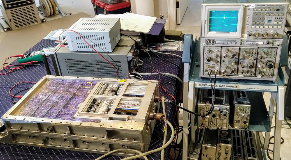
The Apollo Guidance Computer running in Marc's lab, hooked up to a vintage Tektronix scope.

The Apollo Guidance Computer running in Marc's lab, hooked up to a vintage Tektronix scope.

CuriousMarc has a series of AGC videos which you should watch for more information on the restoration project. I announce my latest blog posts on Twitter, so follow me @kenshirriff for future articles. I also have an RSS feed. Thanks to Mike Stewart for supplying images and extensive information.

Notes and references

  1. The AGC restoration team consists of Mike Stewart (creator of FPGA AGC), Carl Claunch, Marc Verdiell (CuriousMarc on YouTube) and myself. The AGC that we're restoring belongs to a private owner who picked it up at a scrapyard in the 1970s after NASA scrapped it. 

  2. In addition to the NOR-gate logic chips, the AGC used a second type of integrated circuit for its memory circuitry, a sense amplifier. (The earlier Block I Apollo Guidance Computer used NOR gate ICs that contained a single NOR gate.) 

  3. How does the AGC stack up to early microprocessors? Architecturally, I'd say it was more advanced than early 8-bit processors like the 6502 (1975) or Z-80 (1976), since the AGC had 15 bits instead of 8, as well as more advanced instructions such as multiplication and division. But I consider the AGC less advanced than the 16-bit Intel 8086 (1978) which has a larger register set, advanced indexing, and instruction queue. Note, though, that the AGC was in a class of its own as far as I/O, with 227 interface circuits connected to the rest of the spacecraft.

    Looking at transistor counts, the Apollo Guidance Computer had about 17,000 transistors in total in its ICs, which puts it between the Z80 microprocessor (8,500 transistors) and the Intel 8086 (29,000 transistors).

    As far as performance, the AGC did a 15-bit add in 23.4μs and a multiply in 46.8μs. The 6502 took about 3.9μs for an 8-bit add (much faster, but a smaller word). Implementing an 8-bit multiply loop on the 6502 might take over 100μs, considerably worse than the AGC. The AGC's processor cycle speed of 1.024 MHz was almost exactly the same as the Apple II's 1.023 MHz clock, but the AGC took 24 cycles for a typical instruction, compared to 4 on the 6502. The big limitation on AGC performance was the 11.7μs memory cycle time, compared to 300 ns for the Apple II's 4116 DRAM chips.  

  4. An AGC instruction fit into a 15-bit word and consisted of a 3-bit opcode and a 12-bit memory address. Unfortunately, both the opcode and memory address were too small, resulting in multiple workarounds that make the architecture kind of clunky.

    The AGC's 15-bit instructions included a 12-bit memory address which could only address 4K words. This was inconvenient since the AGC had 2K words of core RAM and 36K words of core rope ROM. To access this memory with a 12-bit address, the AGC used a complex bank-switching scheme with multiple bank registers. In other words, you could only access RAM in 256-word chunks and ROM in somewhat larger chunks.

    The AGC's instructions had a 3-bit opcode field, which was too small to directly specify the AGC's 34 instructions. The AGC used several tricks to specify more opcodes. First, an EXTEND instruction changed the meaning of the following instruction, allowing twice as many opcodes but wasting a word. Also, some AGC opcodes didn't make sense if performed on a ROM address (such as incrementing), so four different instructions ("quartercode instructions") could share an opcode field. Instructions that act on peripherals only use 9 address bits, freeing up 3 additional bits for opcode use. This allows, for instance, Boolean operations (AND, OR, XOR) to fit into the opcode space, but they can only access peripheral addresses, not main memory addresses.

    The AGC also used some techniques to keep the opcode count small. For example, it had some "magic" memory locations such as the "shift right register". Writing to this address performed a shift; this avoided a separate opcode for "shift right".

    The AGC also had some instructions that wedged multiple functions into a single instruction. For instance, the "Transfer to Storage" instruction not only transferred a value to storage, but also checked the overflow flag and updated the accumulator and skipped an instruction if there had been an arithmetic overflow. Another complex instruction was "Count, Compare, and Skip", which loaded a value from memory, decremented it, and did a four-way branch depending on its value. See AGC instruction set for details. 

  5. For more on the AGC's architecture, see the Virtual AGC and the Ultimate Apollo Guidance Computer Talk

  6. The NAND gate also has the same property of being a universal gate. (In modern circuits, NAND gates are usually more popular than NOR gates for technicalreasons.) The popular NAND to Tetris course describes how to build up a computer from NAND gates, ending with an implementation of Tetris. This approach starts by building a set of logic gates (NOT, AND, OR, XOR, multiplexer, demultiplexer) from NAND gates. Then larger building blocks (flip flop, adder, incrementer, ALU, register) are built from these gates, and finally a computer is built from these building blocks. 

  7. Modern computers usually have a stack that is used for subroutine calling and returning. However, the AGC (like many other computers of its era) didn't have a stack, but stored the return address in a link register (the AGC's Q register). To use recursion, a programmer would need to implement their own stack. 

  8. A carry-skip circuit improves the performance of the adder. The problem with binary addition is that propagating a carry through all the bits is slow. For example, if you add 111111111111111 + 1, the carry from the low-order bit gets added to the next bit. This generates a carry which propagates to the next bit, and so forth. This "ripple carry" causes the addition to be essentially one bit at a time. To avoid this problem, the AGC uses a carry-skip circuit that looks at groups of four bits. If there is a carry in, and each position has at least one bit set, there is certain to be a carry, so a carry-out is generated immediately. Thus, propagating a carry is approximately three times as fast. (With groups of four bits, you'd expect four times as fast, but the carry-skip circuit has its own overhead.) 

  9. You might wonder how the AGC performs a variety of arithmetic and logic operations if the arithmetic unit only supports addition. Subtraction is performed by complementing one value (i.e. flipping the bits) and then adding. Most computers have a complement circuit built into the ALU, but the AGC is different: when the B register is read, it can provide either the value or the complement of the stored value.10 So to subtract a value, the value is stored in the B register and then the complement is read out and added.

    What about Boolean functions? While most computers implement Boolean functions with logic circuitry in the ALU, the Apollo Guidance Computer manages to implement them without extra hardware. The OR operation is implemented through a trick of the register circuitry. By gating two registers onto the write bus at the same time, a 1 from either register will set the bus high, yielding the OR of the two values. AND is performed using the formula A ∧ H = ~(~A ∨ ~H); complementing both arguments, doing an OR, and then complementing the result yields the AND operation. XOR is computed using the formula A ⊕ H = ~(A ∨ ~H) ∨ ~(H ∨ ~A), which uses only complements and ORs. It may seem inefficient to perform so many complement and OR operations, but since the instruction has to take 12 time intervals in any case (due to memory timing), slow down the instruction.

    Multiplication is performed by repeated additions, subtractions, and shifts using a Radix-4 Booth algorithm that operates two bits at a time. Division is performed by repeated subtractions and shifts.11 Since multiply and divide require multiple steps internally, they are slower than other arithmetic instructions. 

  10. Since a latch has outputs for both a bit and the complement of the bit, it is straightforward to get the complemented value out of a latch. Look near the bottom of the schematic to see the B register's circuitry that provides the complemented value. 

  11. The AGC's division algorithm is a bit unusual. Instead of subtracting the divisor at each step, a negative dividend / remainder is used through the division and the divisor is added. (This is essentially the same as subtracting the divisor, except everything is complemented.) See Block II Machine Instructions section 32-158 for details. 

  12. The AGC doesn't use microcode but confusingly some sources say it was microprogrammed. The book "Journey to the Moon" by Eldon Hall (creator of the AGC) says:

    The instruction selection logic and control matrix was a microprogrammed instruction sequence generator, equivalent to a read-only memory implemented in logic. Outputs of the microprogrammed memory were a sequence of control pulses that were logic products of timing pulses, tests of priority activity, instruction code, and memory address.

    This doesn't make sense, since the whole point of microprogramming is to use read-only memory instead of hardwired control logic. (See A brief history of microprogramming, Computer architecture: A quantitative approach section 5.4, or Microprogramming: principles and practices.) Perhaps Hall means that the AGC's control was "inspired" by microprogramming, using a clearly-stated set of sequenced control signals with control hardware separated from the data path (like most modern computers, hardwired or microcoded). (In contrast, in many 1950s computers (like the IBM 1401) each instruction's circuitry generated its own ad hoc control signals.)

    By the way, implementing the AGC in microcode would have required about 8 kilobytes of microcode (79 control pulses for about 70 subinstructions with 12 time periods. This would have been impractical for the AGC, especially when you consider that microcode storage needs to be faster than regular storage.  

  13. While instructions typically used two subinstructions, there were exceptions. Some instructions, such as multiply and divide, required multiple subinstructions because they took many steps. On the other hand, the jump instruction (TC) used a single subinstruction since fetching the next instruction was the only task to do. 

  14. Other processors use different approaches to generate control signals. The 6502 and many other early microprocessors decoded instructions with a Programmable Logic Array (PLA), a ROM-like way of implementing AND-OR logic. The Z-80 used a PLA, followed by logic very similar to the crosspoint generator to generate the right signals for each time step. Many computers use microcode, storing the sequence of control steps explicitly in ROM. Since minimizing the number of chips in the AGC was critical, optimizing the circuitry was more important than using a clean, structured approach.

    Die photo of the 6502 microprocessor. The 6502 used a PLA and random logic for the control logic, which occupies over half the chip. Note the regular, grid-like structure of the PLA. Die photo courtesy of Visual 6502.

    Die photo of the 6502 microprocessor. The 6502 used a PLA and random logic for the control logic, which occupies over half the chip. Note the regular, grid-like structure of the PLA. Die photo courtesy of Visual 6502.


  15. Each subinstruction's actions at each time interval are described in the manual. The control pulses are described in detail in the manual. (The full set of control pulses for ADS0 are listed here.) 

A visit to the Large Scale Systems Museum

$
0
0

I didn't expect to find two floors filled with vintage computers in a sleepy town outside Pittsburgh. But that's the location of the Large Scale System Museum, housed in an abandoned department store. The ground floor of this private collection concentrates on mainframes and minicomputers from the 1970s to 1990s featuring IBM, Cray, and DEC systems, along with less common computers. Amazingly, most of these vintage systems are working. Upstairs, the museum is filled with vintage home computers from the pre-PC era.

IBM

IBM set the standard for the mainframe computer with its introduction of the System/360 in 1964, a line of computers designed to support the full circle (i.e. 360°) of business and scientific applications. The System/360 evolved into the System/370 in the 1970s and the System/390 in the 1990s. Most of these mainframes filled a data center, but the museum has some smaller S/370 and S/390 mainframes designed for offices. The IBM System/370 9375 (1986; below), is described as a "baby mainframe" or "super-mini computer" for engineering or commercial applications.

IBM System/370 9375. The computer itself is in the middle rack. The left rack has a 3490E tape cartridge storage system, while the right rack holds 9335 disk controllers and disk drives (856 MB per drive).

IBM System/370 9375. The computer itself is in the middle rack. The left rack has a 3490E tape cartridge storage system, while the right rack holds 9335 disk controllers and disk drives (856 MB per drive).

The System/390 line is represented by the IBM System/390 Multiprise-2003 (1997; below). This mainframe could not boot up on its own, but required a special desktop PC called the Mainframe Service Element (photo) to initialize the mainframe with microcode and start it up.

This low-end IBM System/390 Multiprise-2003 had 1 GB of memory and supported hundreds of simultaneous database transactions.

This low-end IBM System/390 Multiprise-2003 had 1 GB of memory and supported hundreds of simultaneous database transactions.

To support smaller customers, IBM also produced minicomputers, which they called "midrange systems". The IBM System/32 (1975; below) is a minicomputer built into a desk, designed for small businesses. IBM's midrange systems evolved into the IBM AS/400 (1992; photo).

This IBM System/32 had 16 KB of memory and 13 MB of disk storage. It leased for $1200 per month.

This IBM System/32 had 16 KB of memory and 13 MB of disk storage. It leased for $1200 per month.

The museum has many disk drives and tape drives. One example is the massive 3380E disk drive (below; 1985), providing 5 gigabytes of storage. It's amazing to think that you can now hold a thousand times as much storage in your hand.

The IBM 3380E disk system stored 5 gigabytes of data. The 14-inch disk platter is in the center, labeled "E".

The IBM 3380E disk system stored 5 gigabytes of data. The 14-inch disk platter is in the center, labeled "E".

Cray

Computer designer Seymour Cray and his company Cray Research were famed for building the world's fastest supercomputers. The museum has several Cray computers from the 1990s. The Cray YMP-EL supercomputer (1992; below) was an "Entry Level" Cray, costing $300,000. It was built from CMOS chips rather than the fast but hot ECL chips in earlier Crays, allowing it to be air-cooled rather than Freon cooled. The museum also has the related, low-end Cray EL-94, packaged in an ugly box (photo; 1992);

The Cray YMP-EL supercomputer.

The Cray YMP-EL supercomputer.

The Cray J90 (1996; below) was a popular low-end Cray, an evolution of the Y-MP EL. This one holds 1 GB of memory and cost $300,000.

Cray J 90 supercomputer.

Cray J 90 supercomputer.

The Cray SV1 (1999; below) followed the J90. It introduced more high-performance features such as a vector cache and multi-streaming. This one has 16 processors and 16 GB of memory, and cost about $1 million.

The Cray SV1 supercomputer.

The Cray SV1 supercomputer.

Digital Equipment Corporation (DEC)

Dave McGuire, curator of the large systems, in front of PDP "Straight 8" minicomputers.

Dave McGuire, curator of the large systems, in front of PDP "Straight 8" minicomputers.

Digital Equipment Corporation was founded in 1957 and became the second-largest computer manufacturer, concentrating on minicomputers. DEC's PDP-8 was a very popular 12-bit minicomputer that essentially created the "minicomputer" category of computers. The first PDP-8 was the Straight-8 (1966; photos above and below), a compact all-transistor computer built from circuit cards plugged into a wire-wrapped backplane.

The "Straight 8" PDP-8 was built from transistorized circuits on small cards.

The "Straight 8" PDP-8 was built from transistorized circuits on small cards.

The PDP-8/E (1969; below) used integrated circuits (7400-series TTL) in place of discrete transistors as did the compact and cheaper PDP-8/A (1974; photo).

PDP-8/E minicomputer. The paper tape reader is at the top, above the front panel. An RK05 DECpack is at the bottom, storing 2.4 megabytes on a removable disk pack.

PDP-8/E minicomputer. The paper tape reader is at the top, above the front panel. An RK05 DECpack is at the bottom, storing 2.4 megabytes on a removable disk pack.

DEC started producing mainframes in 1966 with the PDP-10, a 36-bit computer that popularized time-sharing. The museum has a DECsystem-2020 (1978), the smallest member of the PDP-10 family.

A DECsystem-2020 mainframe next to an RM02 disk drive. The drive's removable disk packs each store 67 megabytes.

A DECsystem-2020 mainframe next to an RM02 disk drive. The drive's removable disk packs each store 67 megabytes.

In 1970, DEC introduced the 16-bit PDP-11, which became the most popular minicomputer with about 600,000 sold. The museum has many different PDP-11 models including the PDP-11/05 (1972; photo, console), the fast PDP-11/50 (1972; below, photo), the compact and popular PDP-11/34 (1976; photo), and the PDP-11/44 (1981; photo).

Console of the PDP-11/50 minicomputer.

Console of the PDP-11/50 minicomputer.

DEC's PDP-11 evolved into the VAX line of 32-bit computers. Larger and more powerful than earlier minicomputers, these systems were known as superminicomputers. The VAX-11/780 (1978; below) was the first member of the VAX family, and was implemented with TTL chips. The museum has a VAX-11/750 (1980) and the cheap single-cabinet VAX-11/730 (1982; photo), the powerful VAX-6000 (1991; photo), and top-of-the-line VAX-7000 (1992; photo). The VAXstation 4000 Model 90 (1991; photo) was a workstation implementing the VAX instruction set.

The VAX 11/780 "superminicomputer".

The VAX 11/780 "superminicomputer".

DEC started struggling in the 1990s as the market shifted to personal computers. DEC was acquired in 1998 by personal computer manufacturer Compaq, which in turn was soon acquired by Hewlett-Packard in 2002.

Other systems

The museum has systems from many other companies such as Varian, Control Data, Wang, Panasonic, Silicon Graphics, Singer, and Tektronix, but I'll just touch on some highlights.

Data General was a major producer of minicomputers, third behind DEC and IBM. The Data General Eclipse was the successor to the popular Data General Nova 16-bit minicomputer. It is represented in the museum by the Eclipse S/280 (1975; below) and Eclipse S/120 (1982; photo). Data General moved into the microcomputer market with the microNOVA (1977; photo), but it wasn't commercially successful.

Data General Eclipse S/280 minicomputer.

Data General Eclipse S/280 minicomputer.

In the late 1970s, Hewlett-Packard was the fourth-largest producer of minicomputers. The HP 2116B minicomputer (1968; photo) was part of the HP 1000 (photo) family of 16-bit minicomputers designed for instrument control and automation. The HP 2645A terminal (below) was part of HP's line of terminals.

HP 2645A terminal

HP 2645A terminal

Another interesting terminal is the Friden Flexowriter from the early 1960s (below). It has a paper tape reader and punch on the left. Flexowriters were often used as console terminals for computers.

Friden Flexowriter

Friden Flexowriter

The Burroughs B80 is a multi-user office minicomputer (1978; below). It has as dot-matrix printer above the keyboard. The computer on display was used by a funeral home, and has a paper product list taped above the keyboard with products such as "Tranquility urn", "Open/Close grave", and "Move dirt more than 25 miles".

The Burroughs B80 office minicomputer.

The Burroughs B80 office minicomputer.

The collection also includes analog computers, such as the Heathkit H-1 (1950s) which used vacuum tube amplifiers and represented values by signals from -100 to 100 volts. It could be programmed to solve differential equations by wiring the patch board. The museum also has a Comdyna GP-6 (photo), a more modern transistorized analog computer from the late 1960s.

A Heathkit H1 analog computer. Vacuum tubes are on top, the plugboard is in the middle, and potentiometer controls are in the front.

A Heathkit H1 analog computer. Vacuum tubes are on top, the plugboard is in the middle, and potentiometer controls are in the front.

Microcomputers in the Large Scale Integration Museum

Upstairs is the "Large Scale Integration Museum", a large collection of microcomputers of the 1970s and 1980s. The collection focuses on microcomputers before to the IBM PC and x86 processors. Since I'm more interested in the larger computers, I'll discuss this collection briefly, but I don't want to downplay its impressive scope.

Corey Little, curator of the microcomputer collection, in front of Imsai, ASR-33 teletype, Kenbek-1 replica, and Altair.

Corey Little, curator of the microcomputer collection, in front of Imsai, ASR-33 teletype, Kenbek-1 replica, and Altair.

The first commercial microprocessor was Intel's 4-bit 4004, introduced in 1971. The Intel Intellec 4/40 development system (below), used the 4040 microprocessor (1974), an improved version of the 4004. This system was intended for engineers to develop software for embedded systems using the 4040 chip.

Intel Intellec 4/40 development system. An EPROM socket below the key allowed software to be burned into EPROM chips.

Intel Intellec 4/40 development system. An EPROM socket below the key allowed software to be burned into EPROM chips.

The microcomputer revolution took off when Intel released the 8-bit 8080 microprocessor in 1974, leading to the first commercially successful personal computer, the MITS Altair 8800 kit (1975). In addition to the Altair 8800, the museum has the updated Altair 8800b and the more obscure Altair 680, which uses the Motorola 6800 microprocessor.

Altair 8800 (with the famous manifesto Computer Lib on top), Altair 680, Altair 8800b, and disk drive for Altair.

Altair 8800 (with the famous manifesto Computer Lib on top), Altair 680, Altair 8800b, and disk drive for Altair.

Single-board computers also helped popularize microprocessors. Companies produced development kits for engineers to experiment with new microprocessors and hobbyists often used them due to their low cost. The museum has several racks of these development boards; the rack below includes the Intel SDK-85 System Design Kit for the 8085 microprocessor, Artisan Electronics Model 85 microcalculator (a single-board scientific calculator that could be interfaced to a microcomputer), Rockwell's 6502-based AIM-65, Synertek's 6502-based SYM-1, and Transputer parallel processor boards.

A variety of development boards and single-board computers.

A variety of development boards and single-board computers.

By the late 1970s, microcomputers became mass-market products, with the introduction of home computers that were more affordable and usable by the general public. The museum has many other popular home computers from manufacturers such as Atari, Sinclair, Radio Shack, Heathkit, and Texas Instruments. The photo below shows part of the Commodore collection.

The Commodore collection includes calculators, Commodore Super PET, Educator 64, PET 4032, and PET 2001

The Commodore collection includes calculators, Commodore Super PET, Educator 64, PET 4032, and PET 2001

Early portable computers were suitcase-sized and often called luggables. The museum has a large collection including the IBM 5100 (1975; below), Osborne One (1981), Osborne Executive, Osborne Vixen, and Kaypro II, as well as more obscure machines such as the Telcon Zorba and General Electric Workmaster.

The IBM 5100 portable computer was introduced in 1975, six years before the IBM PC. Its keyboard has special characters for the APL language.

The IBM 5100 portable computer was introduced in 1975, six years before the IBM PC. Its keyboard has special characters for the APL language.

Apple is represented by a variety of Apple II, Apple III, Lisa, and Macintosh systems. The collection also includes a NeXTcube, the workstation developed by Steve Jobs in the 1980s after he was forced out of Apple. Steve Jobs returned to Apple when Apple purchased NeXT in 1997, leading to Apple's dramatic rise. The NeXTcube's operating system led to Apple's current macOS and iOS operating systems.

The NeXTcube workstation was packaged in a 1-foot magnesium cube.

The NeXTcube workstation was packaged in a 1-foot magnesium cube.

The museum has various toys and educational devices that were produced to explain computers, including the CALCULO Analog Computer (1959), Minivac 6010 (1962) created by the father of information theory Claude Shannon, Radio Shack Science Fair Digital Computer Kit (1977), and Digi-Comp 1 (1963).

The collection includes toy computers such as the CALCULO Analog Computer, MINIVAC 6010, Radio Shack ScienceFair Digital Computer, and Digi-Comp 1.

The collection includes toy computers such as the CALCULO Analog Computer, MINIVAC 6010, Radio Shack ScienceFair Digital Computer, and Digi-Comp 1.

Heathkit introduced the HERO-1 kit robot in 1982, providing a way for hobbyists to experiment with robotics. Nowadays, Arduinos and cheap servos and stepper motors make it easy to build a simple robot, but in 1982, robotics was much more difficult. The HERO-1 kit cost $1500 (equivalent to about $4000 today).

Three Heathkit HERO robots. The HERO 2000 (1986, left) included multiple processors and speech synthesis, while the older HERO-1 robots have a single 6808 processor. The "eyes" are an ultrasonic distance sensor.

Three Heathkit HERO robots. The HERO 2000 (1986, left) included multiple processors and speech synthesis, while the older HERO-1 robots have a single 6808 processor. The "eyes" are an ultrasonic distance sensor.

Conclusion

The Large Scale Systems Museum contains a remarkable collection of large computer systems and microcomputers from the 1970s to 1990s The museum, hidden behind a storefront on a quiet small-town main street, illustrates an interesting period in computer history. During this time, mainframes, minicomputers, and supercomputers reached their peak and then went into steep decline. Meanwhile, the microprocessor passed through the hobbyist phase and the home computer phase before achieving its dominance. Amazingly most of the systems at the museum are up and running, giving the visitor a feel for the computers of that era.

The museum is open by appointment only; details are here and on their Facebook page. If you ever find yourself near New Kensington, PA (half an hour outside Pittsburgh), get in touch with them. I've only presented the highlights of the museum; more photos are here. I announce my latest blog posts on Twitter, so follow me @kenshirriff for future articles. I also have an RSS feed.

How "special register groups" invaded computer dictionaries for decades

$
0
0

Half a century ago, the puzzling phrase "special register groups" started showing up in definitions of "CPU", and it is still there. In this blog post, I uncover how special register groups went from an obscure feature in the Honeywell 800 mainframe to appearing in the Washington Post.

While researching old computers, I found a strange definition of "Central Processing Unit" that keeps appearing in different sources. From a book reprinted in 2017:1

"Central Processor Unit (CPU)—Part of a computer system which contains the main storage, arithmetic unit and special register groups. It performs arithmetic operations, controls instruction processing and provides timing signals."

"Central Processor Unit (CPU)—Part of a computer system which contains the main storage, arithmetic unit and special register groups. It performs arithmetic operations, controls instruction processing and provides timing signals."

At first glance, this definition seems okay, but a few moments thought reveals some problems. Storage is not part of the CPU. But more puzzling, what are special register groups? A CPU has registers, but "special register groups" is not a normal phrase.

It turns out that this definition has been used extensively for over half a century, even though it doesn't make sense, copied and modified from one source to another. Special register groups were a feature in the Honeywell 800 mainframe computer, introduced in 1959. Although this computer is long-forgotten2, its impact inexplicably remains in many glossaries. The Honeywell 800 allowed eight programs to run on a single processor, switching between programs after every instruction.3 To support this, each program had a "special register group" in hardware, its own separate group of 32 registers (program counter, general-purpose registers, index registers, etc.).

Honeywell 800 computer. The Central Processing Unit (containing special register groups) is in cabinets 6 feet high and 18 feet wide along the wall. The card reader and printer are in the center of the room. A typical system rented for $25,000 a month. Photo from BRL report, 1961 courtesy of Ed Thelen.

Honeywell 800 computer. The Central Processing Unit (containing special register groups) is in cabinets 6 feet high and 18 feet wide along the wall. The card reader and printer are in the center of the room. A typical system rented for $25,000 a month. Photo from BRL report, 1961 courtesy of Ed Thelen.

Another important thing to note about that era is the central processing unit was a large physical box, also known as the "main frame". (A mainframe was not a type of computer yet.) Thus, given the characteristics of the Honeywell 800, the definition of CPU in Honeywell's glossary4 made total sense.5 Unfortunately, this definition doesn't make sense when used for computers in general, since they lack special register groups.

Honeywell's definition of main frame: "FRAME, MAIN, (I) the central processor of the computer
system. It contains the main storage, arithmetic unit and
special register groups. Synonymous with (CPU) and
(central processing unit). (2) All that portion of a computer exclusive of the input, output, peripheral and in some
instances, storage units."

Honeywell's definition of main frame: "FRAME, MAIN, (I) the central processor of the computer system. It contains the main storage, arithmetic unit and special register groups. Synonymous with (CPU) and (central processing unit). (2) All that portion of a computer exclusive of the input, output, peripheral and in some instances, storage units."

This definition apparently started with the US Department of Agriculture's Glossary of ADP Terminology (1960): "MAIN FRAME - The central processor of the computer system. It contains the main memory, arithmetic unit and special register groups". The definition then spread through the government. The Bureau of the Budget published the Automatic Data Processing Glossary in 1962 "for use as an authoritative reference by all officials and employees of the executive branch of the Government" with the definition below. The Air Force's 1966 Guide for Auditing Automatic Data Processing Systems used a similar definition as did the 1966 Navy Training Course for Machine Accountant and 1968 Air Force manual Communications-Electronics Terminology.

Bureau of the Budget's 1962 definition: "frame, main, (1) the central processor of the computer system. It contains the main storage, arithmetic unit and special register groups. Synonymous with CPU and central processing unit. (2) All that portion of a computer exclusive of the input, output, peripheral and in some instances, storage units."

Bureau of the Budget's 1962 definition: "frame, main, (1) the central processor of the computer system. It contains the main storage, arithmetic unit and special register groups. Synonymous with CPU and central processing unit. (2) All that portion of a computer exclusive of the input, output, peripheral and in some instances, storage units."

From there, the definition spread to dozens of books and dictionaries. The "special register groups" appeared in numerous computer glossaries such as the Glossary of Computing Terminology (1972), Computer Glossary for Medical and Health Sciences (1973) Computer Glossary for Engineers and Scientists (1973), Radio Shack's Dictionary of Electronics (1968, 1974-1975), and Computer Graphics Glossary (1983)

Radio Shack's New 1974-1975 Dictionary of Electronics contains the definition:
"central processing unit—Also called central processor. Part of a computer system which
contains the main storage, arithmetic unit, and special register groups. Performs arithmetic operations, controls instruction processing, and provides timing signals and other housekeeping operations."

Radio Shack's New 1974-1975 Dictionary of Electronics contains the definition: "central processing unit—Also called central processor. Part of a computer system which contains the main storage, arithmetic unit, and special register groups. Performs arithmetic operations, controls instruction processing, and provides timing signals and other housekeeping operations."

Computer manufacturers should know their systems don't have special register groups, but they still used the definition. For example, Sphere microcomputer (1976), Texas Instruments (1978), Cray (1984), Convergent Technologies (1987), and Tektronix (1989).

This definition persisted into the microcomputer age, even though storage was now clearly not part of the CPU and "special register groups" were decades in the past. A 1983 Beginner's Computer Glossary in MICRO magazine defined "CPU — Central Processing Unit. The central processor of the computer system, which contains the main storage, arithmetic unit, and special register groups.""Special register groups" also showed up in Microcomputer Dictionary (1981), and Understanding Microprocessors (1984),

Definitions with "special register groups" appeared in a dizzying array of books, such as Computer Technology in the Health Sciences (1974), College Typewriting (1975), Research Methods for Recreation and Leisure (1979), EPA's Design Automation Handbook for Automation of Activated Sludge Treatment Plants (1980), Patrick-Turner's Industrial Automation Dictionary (1996), Video Scrambling & Descrambling (1998), US Department of Transportation's Computerized Signal Systems (1979). and Traffic Control System Operations (2000).

In 1981, special register groups reached national newspapers in a Washington Post glossary: "Main-frame—central processor of computer system, containing main storage, arithmetic unit and special register groups." By 2006, even the National Fire Code6 included special register groups: "Computer. A programmable electronic device that contains a central processing unit(s), main storage, an arithmetic unit, and special register groups."

Special register groups are still being taught to the next generation of students. The following quiz question is from a 2017 book that teaches computer organization and programming:7

CPU of a computer system does not contain:
(a) Main storage
(b) Arithmetic unit
(c) Special register group
(d) None of the above

Conclusion

For some reason, a 1960 definition of "central processing unit" included "special register groups", an obscure feature from the Honeywell 800 mainframe. This definition was copied and changed for decades, even though it doesn't make sense. It appears that once something appears in an authoritative glossary, people will reuse it for decades, and obsolete terms may never die out.

"Computer operators working with tape-driven Honeywell 800 mainframe computer."
The operators in this photo from the 1960s are presumably taking advantage of the special register groups unique to the Honeywell 800 and 1800 computers.  Photo from National Library of Medicine.

"Computer operators working with tape-driven Honeywell 800 mainframe computer." The operators in this photo from the 1960s are presumably taking advantage of the special register groups unique to the Honeywell 800 and 1800 computers. Photo from National Library of Medicine.

Researching this phrase also shows how the meanings of computer terms shift greatly over time. In 1960, "main frame" and "CPU" were synonyms, but since then they have moved in opposite directions: "mainframe" is now a large computer system, while the "CPU" is usually a processor chip. (I plan to write much more about this.)

I announce my latest blog posts on Twitter, so follow me @kenshirriff for future articles. I also have an RSS feed.

Notes and References

  1. Reference: Reliability Engineering for Nuclear and Other High Technology Systems, CRC Press, 2017, reprint of a book originally published in 1985. 

  2. I happen to be familiar with the Honeywell 800 and 1800 computers because I've been studying the Apollo Guidance Computer extensively. (The Honeywell 1800 was an improved version of the Honeywell 800.) The Honeywell 1800 was used to assemble programs for the Apollo Guidance Computer using an assembler called YUL

  3. The Honeywell 800's technique of switching programs on every instruction is rather unusual. Typical multi-tasking systems let a program run for several milliseconds before switching to another program to reduce the overhead of switching between programs. The Honeywell 800 Programmers Reference Manual explains the use of special register groups for multiprogramming. 

  4. Honeywell's Glossary of Data Processing and Communications Terms was published 1964-1966. Definitions in that book are largely based on the Bureau of the Budget's Automatic Data Processing Glossary. 

  5. The Oxford English Dictionary (1989) quoted the 1964 Honeywell definition. 

  6. Reference: NFPA's Illustrated Dictionary of Fire Service Terms, published by the National Fire Protection Association in 2006. The National Fire Codes (1995) had a somewhat similar definition, but for the CPU instead of computer: "CPU. Central processing unit of the computer system. The CPU contains the main storage, arithmetic unit, and special register groups." 

  7. Reference: Computer Architecture, 2011, published by Biyani. Page 58 contains the quiz with the CPU question. The question also appears in MCS-012: Computer Organisation and Assembly Language Programming, 2017. 

IBM, sonic delay lines, and the history of the 80×24 display

$
0
0

What explains the popularity of terminals with 80×24 and 80×25 displays? A recent blog post "80x25" motivated me to investigate this. The source of 80-column lines is clearly punch cards, as commonly claimed. But why 24 or 25 lines? There are many theories, but I found a simple answer: IBM, in particular its dominance of the terminal market. In 1971, IBM introduced a terminal with an 80×24 display (the 3270) and it soon became the best-selling terminal, forcing competing terminals to match its 80×24 size. The display for the IBM PC added one more line to its screen, making the 80×25 size standard in the PC world. The impact of these systems remains decades later: 80-character lines are still a standard, along with both 80×24 and 80×25 terminal windows.

In this blog post, I'll discuss this history in detail, including some other systems that played key roles. The CRT terminal market essentially started with the IBM 2260 Display Station in 1965, built from curious technologies such as sonic delay lines. This led to the popular IBM 3270 display and then widespread, inexpensive terminals such as the DEC VT100. In 1981, IBM released a microcomputer called the DataMaster. While the DataMaster is mostly forgotten, it strongly influenced the IBM PC, including the display. This post also studies reports on the terminal market from the 1970s and 1980s; these make it clear that market forces, not technological forces, led to the popularity of various display sizes.

Some theories about the 80×24 and 80×25 sizes

Arguments about terminal sizes go back decades,5 but the article 80x25 presented a detailed and interesting theory. To summarize, it argued that the 80×25 display was used because it was compatible with IBM's 80-column punch cards,1 fits nicely on a TV screen with a 4:3 aspect ratio, and just fit into 2K of RAM. This led to the 80×25 size on terminals such as the DEC VT100 terminal (1978). The VT100's massive popularity led to it becoming a standard, leading to the ubiquity of 80×25 terminals. At least that's the theory.

It's true that 80-column displays were motivated by punch cards4 and the VT100 became a standard,2 but the rest of this theory falls apart. The biggest problem with this theory is the VT100's display was 80×24, not 80×25.3 In addition, the VT100 used extra bytes of storage for each line, so the display memory did not fit into 2K. Finally, up until the 1980s, most displays were 80×24, not 80×25.

The DEC VT100 terminal had an 80×24 display. Over a million of them were sold. Photo from Jason Scott, (CC BY-SA 4.0).

The DEC VT100 terminal had an 80×24 display. Over a million of them were sold. Photo from Jason Scott, (CC BY-SA 4.0).

Other theories have been expressed on Software Engineering StackExchange and Retrocomputing StackExchange, arguing that 80×24 terminals resulted from technical reasons such as TV scan rates, aspect ratios, memory sizes, typography, the history of typewriters, and so forth. There is a fundamental problem with theories that 80×24 is an inevitable consequence of technology, though: terminals in the mid-1970s had dozens of diverse screen sizes such as 31×11, 42×24, 50×20, 52×48, 81×38, 100×50, and 133×64.11 This makes it clear that technological limitations didn't force terminals into a particular size. To the contrary, as technology improved, most of these sizes disappeared and terminals were largely 80×24 by the early 1980s. This illustrates that standardization was the key factor, not the technology.

I'll briefly summarize why technical factors don't have much impact on the terminal size. Although US televisions used 525 scan lines and 60 Hz refresh,9 40% of terminals used other values.6 The display frequency and bandwidth didn't motivate a particular display size because terminals generated characters with a wide variety of matrix sizes.8 Although memory cost was significant, DRAM chip sizes quadrupled every three years, making memory only a temporary constraint. The screen's aspect ratio wasn't a big factor because the text's aspect ratio often didn't match the screen's ratio.7 Of course technology had some influence, but it didn't stop early manufacturers from creating terminal sizes ranging from 32×8 to 133×64.

The rise of CRT terminals

At this point, a bit of history of CRT terminals will help.11 Many readers will be familiar with ASCII terminals, such as stand-alone terminals like the DEC VT100, serial terminal connections via a PC, or the serial port on boards such as the Arduino. This type of terminal has its roots in teleprinters, electro-mechanical keyboard/printers that date back to the early 1900s. The best-known teleprinter is the Teletype, popular in newsrooms as well as computer systems in the 1970s. (The Linux device /dev/tty is named after the Teletype.) Teletypes typically printed 72-character lines on a roll of paper.10

A Teletype ASR33 communicated in ASCII and printed 72 characters per line. Hundreds of thousands of these were produced from 1963 to 1981. The punched tape reader and punch is on the left. Photo from Arnold Reinhold, (CC BY-SA 3.0).

A Teletype ASR33 communicated in ASCII and printed 72 characters per line. Hundreds of thousands of these were produced from 1963 to 1981. The punched tape reader and punch is on the left. Photo from Arnold Reinhold, (CC BY-SA 3.0).

In the 1970s, replacing teleprinters with CRT terminals was a large and profitable market. AT&T introduced the Teletype Model 40 in 1973, a CRT terminal with an 80×24 display.12 Many other companies introduced competing CRT terminals, and "Teletype-compatible" became a market segment. By 198111 these terminals were being used in many roles besides replacing teleprinters and the name shifted to "ASCII terminals". By 1985, CRT terminals were a huge success with 10 million terminals installed in the US.

The IBM 3270 terminal, specifically the newer 3278 model. From IBM 3270 Brochure (1977).

The IBM 3270 terminal, specifically the newer 3278 model. From IBM 3270 Brochure (1977).

But there's a parallel world of mainframe terminals, a world that may be unfamiliar to many readers. In 1965, IBM introduced the IBM 2260 Display Terminal, which placed IBM's "stamp of approval" on the CRT terminal, which had previously been "somewhat of a novelty."6 This terminal dominated the market until IBM replaced it with the cheaper and more advanced IBM 3270 terminal in 1977. Unlike asynchronous ASCII terminals that transmitted individual keystrokes, these terminals were block oriented, efficiently exchanging large blocks of characters with a mainframe. The 3270 terminal was fairly "intelligent": a 3270 user could fill in labeled fields on the screen, and then transmit all the data at once by pressing the "Enter" key. (This is why modern keyboards often still have the "Enter" key.) Sending a block of data was more efficient than sending each keystroke to the computer, and allowed mainframes to support hundreds of terminals. In the next sections, I'll discuss the 2260 and 3270 terminals in detail.

The chart below6 shows how the terminal market looked in 1974. The market was ruled by IBM's 3270 terminal, which had obsoleted IBM's 2260 terminal by this point. With 50% of the market, IBM essentially defined the characteristics of a CRT terminal. Teleprinter replacement was a large and influenetial market; the Teletype Model 40 was small but growing in importance. Although DEC would soon be a major player, it was in the small "Independent Systems" slice at this point.

In 1974, IBM dominated the terminal market; 50% of the terminals sold were IBM terminals (or compatibles). From Alphanumeric and Graphic CRT Terminals.

In 1974, IBM dominated the terminal market; 50% of the terminals sold were IBM terminals (or compatibles). From Alphanumeric and Graphic CRT Terminals.

The IBM 2260 video display terminal

The IBM 2260 was introduced in 1965 and was one of the first video display terminals.14 It filled three roles: remote data entry (in place of punching cards), inquiry (e.g. looking up records in a database), and as a system console. This compact terminal weighed 45 pounds and was sized to fit on a standard office typewriter stand. Note the thickness of the keyboard; it reused the complex keyboard mechanism of the IBM keypunch.13

IBM 2260 Display Station. Photo from IBM via Frank da Cruz.

IBM 2260 Display Station. Photo from IBM via Frank da Cruz.

You might wonder how IBM could produce such a compact terminal with 1965 technology. The trick was that the terminal held just the keyboard and CRT display; all the control logic, character generation, storage, and interfacing was in a massive 1000 pound cabinet (below).15 This cabinet contained the circuitry to handle up to 24 display terminals. It generated the pixels for these terminals and send video signals to the terminals, which could be up to 2000 feet away.

The IBM 2848 Display Control could drive up to 24 display terminals.
The cabinet was 5 feet wide and weighed 1000 pounds.

The IBM 2848 Display Control could drive up to 24 display terminals. The cabinet was 5 feet wide and weighed 1000 pounds.

One of the most interesting features of the 2260 is the sonic delay lines used for pixel storage. Bits were stored as sound pulses sent into a nickel wire, about 50 feet long. The pulses traveled through the wire and came out the other end exactly 5.5545 milliseconds later. By sending a pulse (or not sending a pulse for a 0) every 500 nanoseconds, the wire held 11,008 bits. A pair of wires created a buffer that held the pixels for 480 characters.16

The sonic delay line had several problems. First, you had to constantly refresh the data: as bits came out one end of the wire, you had to feed them back in the other end. Second, the delay line was not random access: if you wanted to update a character, you needed to wait several milliseconds for those bits to circulate. Third, the delay line was sensitive to vibration; Wikipedia says that heavy footsteps could mess up the screen. Fourth, the delay line speed was sensitive to temperature changes; it needed to warm up for two hours in a temperature-controlled cabinet before use. With all these disadvantages, you might wonder why sonic delay lines were used. The main reason was they were much cheaper than core memory. The serial nature of a delay line was also a good match to the serial nature of a raster-scan display.

Sonic delay line module from the IBM 2260 display. This module contained about 50 feet of coiled nickel wire. Image from 2260 Field Engineering Theory of Operation Manual.

Sonic delay line module from the IBM 2260 display. This module contained about 50 feet of coiled nickel wire. Image from 2260 Field Engineering Theory of Operation Manual.

The image below shows the screen of the 2260 Model 2, with 12 lines of 40 characters. (The Model 1 had 6 lines of 40 characters and the Model 3 had 12 lines of 80 characters.) Notice that the lines are double-spaced; this is because the control unit actually generated 24 lines of text but alternating lines went to two different terminals.20 This is a very strange approach, but it split the high cost of the control hardware across two terminals.19 Another strange characteristic was that the 2260's scan lines were vertical, unlike the horizontal scan lines in almost every video display and television.21

IBM 2260 display showing 12 lines of 40 characters. Image from 2260 Operator Manual.

IBM 2260 display showing 12 lines of 40 characters. Image from 2260 Operator Manual.

Each character was represented in 6-bit EBCDIC, giving a character set of 64 characters (no lower-case). 18 The delay lines stored the pixels to be displayed, but they also stored the EBCDIC code for each character. The trick here is the blank column of pixels between each character for horizontal spacing between characters. The system used this column to store the BCD character value but blanked the display during this column so the BCD value didn't show up as pixels on the screen. This allowed the 6-bit character value to be stored essentially for free.

The relevant question is why did the 2260 have a display with 12 lines of 80 characters?2324 The 80-character width allowed the terminals to take the place of 80-column punch cards for data entry. (In the 40-character models, a card would be split across two lines.) As for the 12 lines, that appears to be what the delay lines could support without flicker.22

Image from 2260 Operator Manual.

The IBM 2260 was a big success, and led to the popularity of the CRT terminal. The impact of the IBM 2260 terminal is shown by a 1974 report on terminals; about 50 terminals were listed as compatible with the IBM 2260. The IBM 2260 didn't have an 80×24 display (although it generated 80×24 internally), but its 40×12 and 80×12 displays made 80×24 the next step for IBM.

The IBM 3270 video display

In 1971, IBM released the IBM 3270 video display system, which proceeded to dominate the market for CRT terminals.26 This terminal supported a 40×12 display to provide a migration path from the 2260, but also supported a larger 80×24 display. The 3270 had more features than the 2260, such as protected fields on the screen, more efficient communication modes, and variable-intensity text. It was also significantly cheaper than the 2260, ensuring its popularity.25

The IBM 3270 terminal. The Selector Light Pen was used to select data fields, somewhat like a mouse. This terminal is a later model, the 3278; in the photo it is displaying 43 lines of 80 characters. From IBM 3270 Brochure (1977).

The IBM 3270 terminal. The Selector Light Pen was used to select data fields, somewhat like a mouse. This terminal is a later model, the 3278; in the photo it is displaying 43 lines of 80 characters. From IBM 3270 Brochure (1977).

The technology in the 3270 was a generation more advanced than the 2260, replacing vacuum tubes and transistors with hybrid SLT modules, similar to integrated circuits. Instead of sonic delay lines, it used 480-bit MOS shift registers.27 The 40×12 model used one bank of shift registers to store 480 characters. In the larger model, four banks of shift registers (1920 characters) supported an 80×24 display. In other words, the 3270's storage was in 480-character blocks for compatibility with the 2260, and using four blocks resulted in the 80×24 display. (Unlike RAM chips, a shift register size didn't need to be a power of 2. While a RAM chip is arranged as a matrix, a shift register has a serpentine layout (below) and can be an arbitrary size.)

Die photo of the Intel 1405 shift register. This shift register was not used in the IBM 3270 but was used in other terminals such as the Datapoint 2200.

Die photo of the Intel 1405 shift register. This shift register was not used in the IBM 3270 but was used in other terminals such as the Datapoint 2200.

IBM provided extensive software support for the 3270 terminal.28 This had an important impact on the terminal market, since it forced other manufacturers to build compatible terminals if they wanted to compete. In particular, this made 3270-compatibility and the 80×24 display into a de facto standard. In 1977, IBM introduced the 3278, an improved 3270 terminal that supported 12, 24, 32, or 43 lines of data. It also added a status line, called the "operator information area". The new 32- and 43-line sizes didn't really catch on, but the status line became a common feature on competing terminals.

Looking at industry reports61132 shows the popularity of various terminal sizes from the 1970s to the 1990s. Although there were 80×25 displays in 1970 (if not earlier), the 80×24 display was much more common. The wide variety of terminal sizes in 1974 diminished over time, with the market converging on 80×24. By 1979, the DEC VT100 (with its 80×24 display) was the most popular ASCII terminal with over 1 million sold. Terminals started supporting 132×24 for compatibility with 132-character line printers,29 especially as larger 15" monitors became more affordable, but 80×24 remained the most popular size. Even by 1991, 80×25 remained relatively uncommon.

The IBM PC and the popularity of 80×25

Given the historical popularity of 80×24 terminals, why do so many modern systems use 80×25 windows? That's also due to IBM: the 80×25 display became popular with the introduction of the IBM PC in 1981. The PC's default display card (MDA) provided 80×25 monochrome text while the CGA card provided 40×25 and 80×25 in color. This became the default size of a Windows console, as well as the typical size for PC-based terminal windows.

The IBM PC with an 80×25 display generated by the MDA (Monochrome Display Adapter) card. Photo from Boffy b (CC BY-SA 3.0).

The IBM PC with an 80×25 display generated by the MDA (Monochrome Display Adapter) card. Photo from Boffy b (CC BY-SA 3.0).

Other popular computers at the time used 24 lines, such as the Osborne 1 and Apple II, so I was curious why the IBM PC used 25 lines. To find out, I talked to Dr. Dave Bradley and Prof. Mark Dean, two of the original IBM PC engineers. They explained that the IBM PC was a follow-on to the rather obscure IBM DataMaster office computer,30 and many of the IBM PC design choices followed the DataMaster microcomputer. The IBM PC kept the DataMaster's keyboard, but detached from the main unit. Both systems used BASIC, but the decision to get the PC's BASIC interpreter from the tiny company Microsoft would change both companies more than anyone could imagine. Both systems went with an Intel processor, an 8-bit 8085 in the DataMaster and the 16-bit 8088 in the IBM PC. They also used the same interrupt controller, DMA controller, parallel port, and timer chips. The PC's 62-pin expansion bus was almost identical to DataMaster's.

The IBM DataMaster System/23 was a microcomputer announced in 1981 just a month before the IBM PC.

The IBM DataMaster System/23 was a microcomputer announced in 1981 just a month before the IBM PC.

The drawing below is part of an early design plan for the IBM PC. In particular, the IBM PC was going to use the 80×24 display of the DataMaster (codenamed LOMA), as well as 40×16 and 60×16 more suitable for televisions. The drawings also show color graphics with 280×192 pixels, the same resolution as the Apple II. But the IBM PC ended up not quite matching this plan.

Detail from an early (August 25, 1980) design plan for the IBM PC. "LOMA" is the code name for the IBM DataMaster. "18 kHz" is the 18.432 kHz horizontal scan frequency used by the MDA card, providing more resolution than the 15.750 kHz used by NTSC televisions. Scan courtesy of Dr. Dave Bradley.

Detail from an early (August 25, 1980) design plan for the IBM PC. "LOMA" is the code name for the IBM DataMaster. "18 kHz" is the 18.432 kHz horizontal scan frequency used by the MDA card, providing more resolution than the 15.750 kHz used by NTSC televisions. Scan courtesy of Dr. Dave Bradley.

The designers of the IBM PC managed to squeeze a few more pixels onto the display to get 320×200 pixels. When using an 8×8 character matrix, the updated graphics mode supported 40×25 text, while the double-resolution graphics mode with 640×200 pixels supported 80×25 text. The monochrome graphics card (MDA) matched this 80×25 size. In other words, the IBM PC ended up using 80×25 text because the display provided enough pixels, and it provided differentiation from other systems, but there wasn't an overriding motivation. In particular, the designers of the PC weren't constrained by compatibility with other IBM systems.31

Conclusion

To summarize, many theories have been proposed giving technical reasons why 80×24 (or 80×25) is the natural size for a display. I think the wide variety of display sizes in the early 1970s proves this technological motivation is mostly wrong. Instead, display sizes converged on what IBM produced, first with the punch card, then the IBM 2260 terminal, the IBM 3270, and finally the IBM PC. The 72-column Teletype had some influence on terminal sizes at first, but this size was also swept away by IBM compatibility. The result is the current situation with an uneasy split between 80×24 and 80×25 standards.

Thanks to Dr. Dave Bradley, Prof. Mark Dean, and IBM engineer Iggy Menendez for information. I announce my latest blog posts on Twitter, so follow me @kenshirriff for future articles. I also have an RSS feed.

Notes and References

  1. Punch cards have a longer history than you might think. The standard 80-column IBM punch card was introduced in 1928, improving on punch cards used for the 1890 census. Before the modern computer, punch cards were processed with electromechanical sorters and accounting machines. The punch card remained a keystone of data processing until the 1970s, and its impact still remains.

    An IBM punch card holds 80 characters, printed along the top. The hole pattern in each column encodes the character.

    An IBM punch card holds 80 characters, printed along the top. The hole pattern in each column encodes the character.


  2. By 1986, the DEC VT100 was "an acknowledged standard in the terminal industry" and "the most popular ASCII terminal ever produced, with 1,000,000 units sold since its introduction in 1978." 

  3. For information on the internals of the VT100 see the Technical Manual. The VT100 had 3K of memory, of which about 2.3K was used for the screen while the 8080 microprocessor used the remainder. Each line was stored in memory with 3 additional bytes on the end, used as pointers for scrolling. 

  4. It should be clear that IBM's 80-column punch cards were the motivation for 80-column displays, but I wanted to find contemporary sources to confirm that. One example is All About CRT Display Terminals (1974, page 11) stating that terminals with an 80-column line gave compatibility with punched cards while the 72-column line provided compatibility with Teletypes. Also see Big Screen, 132-Column Units Setting Trend, Computerworld, Oct 26, 1981. Although the article focuses on 132-column terminals to replace printers, the article also describes how earlier terminals had an 80-column format like the punch cards they replaced. 

  5. Controversy over the reason for 80×24 displays goes way back. An editorial in Infoworld (Nov 2, 1981) argued that microcomputers shouldn't be locked into the "arbitrary" 80×24 size. This led to angry letters to the editor in Infoworld, Nov 30, 1981, arguing that 80×24 wasn't arbitrary. Writers explained that 80-columns were motivated by punch cards, 24 (or sometimes 25) lines were motivated by tradeoffs in CRT technology, and memory size didn't have much to do with it. 

  6. A detailed source of information on terminals is a 1975 report Alphanumeric and Graphic CRT Terminals

  7. The CRT's aspect ratio matters less than people think. The first reason is that even on a CRT with a 4:3 aspect ratio, many terminals displayed text with a very different aspect ratio by leaving part of the screen blank. The second reason is that terminals could use a custom CRT size if they wanted Although most terminals used a CRT with the standard 4:3 aspect ratio, the actual text could have a very different aspect ratio. Moreover, a custom CRT wasn't out of the question. For instance, the Datapoint 2200 had an unusually wide CRT, designed to match the shape of a punch card. (Reference: Datapoint: The lost story of the Texans who invented the personal computer revolution chapter 4.) The popular Teletype Model 40 also had an unusually wide CRT, with an aspect ratio over 2:1 (photos), which was used for an 80×24 display. 

  8. A raster-scan terminal makes each character out of a matrix of dots. In 1975, a 5×7 or 7×9 matrix was most common.6 (The matrix was often padded with space between characters. For instance, the Apple II used a 5x7 dot matrix padded to a 7×8 field.) Some systems (such as IBM's CGA card) used an 8×8 matrix without padding to supporting graphical characters that touched. Other systems used a much larger character matrix; the IBM Datamaster used 7×9 characters in a 10×14 field, while the Quotron 800 had a 16×20 matrix. The point is that 80×24 terminals can require a wildly varying number of pixels, depending on the matrix selected. This is the flaw in the argument that the bandwidth and scanlines of a display motivated 80×24 terminals; you get a completely different answer depending on the matrix size you pick. 

  9. Home computers in the 1980s often used standard NTSC televisions as displays, so they had to deal with more constraints that terminals. As a result, they often had 40- or 64-character lines, rather than 80, as shown by the Wikipedia list. Also see a Retrocomputing StackExchange discussion

  10. One Retrocomputing StackExchange answer claims that terminals with 72-character lines show "the struggle for 80 characters", with 72-character terminals falling short of the 80-character goal. However, 72-character lines were a deliberate choice to capture the lucrative Teletype market; teleprinters such as the Teletype Model 33 printed 72-character lines. (The model number of the Datapoint 3300 (1969), for instance, reflects the Teletype Model 33.) 

  11. For an extremely detailed look at the terminal industry from 1974 to 1991, see the Datapro reports on Bitsavers. These reports discuss the overall market, as well as thoroughly describing every terminal being marketed. 

  12. AT&T's Teletype Model 40 is mostly forgotten now, but it had a significant impact at the time. AT&T combined the Model 40 with a new, faster communications network called "Dataspeed 40", raising fears that AT&T would monopolize data communications. It is (said that this "spread waves of apprehension that penetrated the very foundation of the communications terminal industry." AT&T targeted IBM's 3270 terminals with the Model 40/4 (which probably explains Model 40's 80×24 display). Complex antitrust litigation against AT&T resulted, which I think blunted the long-term impact of the Model 40. 

  13. The IBM 2260 terminal reused the keyboard of the IBM 26 keypunch (1949). To convert a keypress into a hole pattern, the keypunch keyboard used a complex system of pull-bars, permutation bars (which encode key values in metal tabs), bails, contacts, interlock disks, and restoring electromagnet. Each key triggers 12 contacts; in the keypunch these controlled the 12 holes in each card column, while in the terminal these encode two 6-bit codes, one for shifted and one for non-shifted. This mechanism was much more complex than a "modern" keyboard but it had the advantage of generating key codes without requiring any electronics. (I've written about keypunch internals before.) 

  14. Vector graphics displays predate video terminals by many years, used on systems such as Whirlwind (1951) and SAGE (1958) and later the IBM 2250 Graphics Display Unit (1964). These systems drew arbitrary lines on the screen, rather than pixels. Although these systems could display characters (drawn from line segments), they were very expensive and usually used for graphics, not as character-based terminals.  

  15. The CRT/keyboard unit was called the IBM 2260 Display Station, while the large cabinet with the circuitry was called the IBM 2848 Display Control. People often referred to the complete system as the 2260; I'll follow this usage. 

  16. I'll explain more about the delay line buffers in this footnote. A delay line provided a bit every 500 nanoseconds. Two delay lines were interleaved in a buffer to provide bits twice as fast: every 250 nanoseconds. Data was formatted as 256 "slots", one per vertical scan line. (These slots were purely conceptual since the delay line provided an undifferentiated stream of bits.) 240 slots held data, while 16 were blank for horizontal retrace time. Each slot held 86 bits: 7 bits for 12 rows of characters, along with two parity bits. (Since each scan line was split across two displays, the slot corresponded to 6 characters on the even display and 6 on the odd display.) Six slots made up a vertical line of characters: one slot holding the "BCD" character value, and five slots holding pixels. Thus, each buffer holds data for 480 characters and supported two 40×6 displays. Two buffers supported a pair of 40×12 displays and four buffers supported a pair of 80×12 displays. Details are in the 2260 Field Engineering Theory of Operation Manual, page 2-14. 

  17. A delay line can't be paused—the bits keep flowing, even during vertical and horizontal refresh times. The problem is that you can't display anything during refresh, since the electron beam is swinging back to the start, so what do you do with the pixels the display line provides during that time. The 2260 used two solutions. Horizontal refresh was straightforward, "wasting" delay line bits during the horizontal refresh time. Specifically, a pair of buffers held 512 scan lines; 480 were used for character data while 32 were unusable because horizontal refresh happened while they were being read.

    The interaction between the delay lines and vertical refresh is somewhat complicated. The vertical refresh time was designed to be exactly the same as the 5.5545ms time it took a buffer to fully circulate, while the time to display a vertical scan line was exactly twice this time. Two buffers were interleaved to provide the vertical scan lines. During the first time interval, the first buffer provided pixels for the top half of the line. During the second time interval, the second buffer provided pixels for the bottom half of the line. The third time interval was used for vertical refresh. This pattern continued until the end of the buffers, so every third slot in a buffer was displayed while the "unused" pixels were recirculated. This process was repeated three times, offsetting the start point in the buffer, so the buffers were displayed entirely. 

  18. Another curious feature of the IBM 2260 display is how it converted the 6-bit character code into the 5×7 block of pixels representing the character. It used a special core memory plane that only had cores for 1 bits and omitted cores for 0 bits, so it acted as a read-only memory. The result is you could actually see the characters in core plane, as illustrated below. The core plane holds nine 7-bit words for each of the 64 characters: the first five words held the pixel block, while the four other words were a lookup table to convert the EBCDIC character code (2848 code) to or from ASCII or a tilt-shift code used to control the Selectric-like printer (Model 1053).

    Part of the character generation core plane, showing the segment for the character 'A'.
The diagonal lines indicate ferrite cores; I've colored the cores storing the character image.
The core plane was a 72×56 grid in total representing 64 characters.
Image based on 2260 Field Engineering Theory of Operation Manual p2-82.

    Part of the character generation core plane, showing the segment for the character 'A'. The diagonal lines indicate ferrite cores; I've colored the cores storing the character image. The core plane was a 72×56 grid in total representing 64 characters. Image based on 2260 Field Engineering Theory of Operation Manual p2-82.


  19. IBM apparently liked the idea of splitting display hardware between two users, because they did that with the IBM 3742 Dual Data Station (1973). This system let two operators enter data onto 8" floppy disks. The bizarre part is that it had a single vertically-mounted CRT display. The small black box in the middle of the desk is a pair of mirrors that showed half the screen to each operator. The result was a very squat display with just three lines of 40 characters, enough for a status line and 80 characters of data.

    The IBM 3742 Dual Data Station allowed two operators to type data onto floppy disks. Image from IBM 3740 System Summary.

    The IBM 3742 Dual Data Station allowed two operators to type data onto floppy disks. Image from IBM 3740 System Summary.


  20. The lines of text in the screenshot appear closer together than double-spaced, even though they are double-spaced. The reason is that the dots on the screen are a bit larger than one pixel, so they encroach into the space between the lines. In other words, the display alternates 7 lines of character pixels and 7 blank lines, but it looks more like 9 lines of character pixels and 5 blank lines. 

  21. Televisions and CRT displays normally use a raster scan, scanning the electron beam across the screen in horizontal scan lines, making a series of lines from top-to-bottom. The 2260, on the other hand, has highly-unusual vertical scan lines; the scan lines are top-to-bottom, and the series of lines progressed left-to-right across the screen. I haven't been able to determine any reason why the 2260 has vertical scanlines. I assume it made the timing work out better somehow.  

  22. Here are my calculations on the maximum number of lines that could be displayed by the 2260. A 250 nanosecond pixel rate and 30 Hertz refresh give a maximum of 13,333 pixels that can be displayed on the screen. If each character is 6×7 pixels and there are 80 characters per line, 39.7 lines could be on the screen. Vertical refresh takes 1/3 of the time because of interaction with the delay lines,17 dropping this to 26.5 lines. Because the 2260 splits pixels across two displays, that yields at most 13.25 lines on the display, ignoring horizontal refresh. Therefore, 12 lines of text are about what the hardware could support. (I should point out that it's possible they decided on 12 lines first and selected the other design characteristics to fit this.) Note that the next reasonable line size would be 16 lines. The low-end model displayed 6 lines of 40 characters (i.e. 3 punch cards), so the next step for it would be 8 lines of 40 characters (four punch cards). Since the high-end model uses four buffers, that would yield 16 lines. The point is that it would have been a large jump to go beyond 12 lines. 

  23. The 2260 came in three models. Model 1 displayed 6 lines of 40 characters. Model 2 displayed 12 lines of 40 characters. Model 3 displayed 12 lines of 80 characters. The main difference in implementation was that they used 1, 2, and 4 buffers respectively. The 40-character models refreshed at 60 Hz rather than 30 Hz, since they had half the (vertical) scanlines. 

  24. The aspect ratio of the IBM 2260's text was very different from the screen's aspect ratio. With the bezel, the screen's useful display area is 9.5 by 5.7 inches (5:3 ratio). Note that the aspect ratio of the text was very different from a standard 4:3 ratio. The 40×6 display format is 6.5 by 2.25 inches (almost 3:1 ratio). The 40×12 display format is 6.5 by 4.5 inches (a bit over 4:3 ratio). The 80×12 display format is 9 by 3 inches (3:1 ratio). Information on the 2260's screen size is in the FE Manual chapter 2. 

  25. The 1974 Datapro report gives the price for the IBM 2260 system as $1270 to $2140 for the display unit and $15,715 to $86,365 for the controller. The IBM 3270 in comparison was $4,000 to $7,435 for the display unit (3277) and $6,500 to $15,725 for the controller. Note that compared to the 2260, the 3270 moved much of the complexity from the controller to the display unit, which is reflected in the prices. 

  26. The IBM 3270 was a line of terminals. Like the 2260, it consisted of a Control Unit (3271 or 3272) along with the terminals (3275 or 3277 Display Stations). These could display 40×12 or 80×24. For simplicity, I'll refer to the whole system as the 3270. Over the years, IBM introduced more models in the 3270 line, including color and graphics terminals, supporting lower case as well as display sizes such as 80×32, 80×43, and 132×27. The 3270 PC (1987) was an enhanced IBM PC that acted as a 3270 terminal. However, I'm going to focus on the original 3270 terminals, since those had the most influence. 

  27. A 480-bit shift register might seem like a strange size, since it's not a power of two. However, since shift registers don't have address bits, they can be arbitrary sizes. For instance, Collins made dual 66-bit shift registers, to support 64-bit data plus 2 parity bits. Fairchild made 480-bit shift registers for CRT displays. 500-bit shift registers were built "to operate in equipment where storage lengths in 100 bit multiples are required."Texas Instruments built dynamic bipolar shift registers in 253-bit, 349-bit, and 501-bit sizes which were useful for Digital Differential Analyzers. The point is that shift registers can be built in arbitrary sizes, so there is no need to use a power of two.

    Schematic symbol for the 480-bit shift register in the 3270. Inputs are data and the two-phase clock. "SPEC" indicates a special circuit. From the ALD, page MP151.

    Schematic symbol for the 480-bit shift register in the 3270. Inputs are data and the two-phase clock. "SPEC" indicates a special circuit. From the ALD, page MP151.

    The 3270 used banks of ten 480-bit shift registers to store 480 10-bit data words (9 bits and parity), unlike the earlier 2260 delay lines, which stored pixels. 

  28. Software support for the 3270 included DIDOCS (Device Independent Display Operator Console Support), using the 3270 as a mainframe system console; VIDEO/370 (Visual Data Entry Online), a program that allowed customers to design forms for data entry; DATA/360, a program that emulated an IBM 29 card punch, but provided editing and validation; IMS (Information Management System); (CICS) Customer Information Control System, which allowed interaction with a database; IQF (Interactive Query Facility), another database system; and TSO (Time Sharing Option). 

  29. The 132-column width for terminals was motivated by the ubiquity of IBM's 132-column printers.) 

  30. The DataMaster's influence on the IBM PC is described in two articles by Dr. Dave Bradley: The creation of the IBM PC in Byte, Sept. 1990; and A personal history of the IBM PC, IEEE Computer, Aug 2011 (paywalled). The Wikipedia article DataMaster System/23 also provides information. 

  31. Dr. Bradley explained that the designers of the IBM PC weren't concerned with compatibility with other systems. For instance, you might expect the IBM PC to be compatible with the 3270 terminal. However, the IBM PC's keyboard had 10 function keys while the IBM 3270 terminal had 12. This incompatibility was finally fixed with the IBM PS/2 keyboard (1987). 

  32. To confirm the popularity of 80×24 terminals versus 80×25 terminals, I took a look at the GNU termcap file. I counted and found there were over 5 times as many 24-line terminals as 25-line terminals, and the 25-line terminals were mostly PC-based. 80-column terminals were over 5 times as popular as 132-column terminals, the runner-up. 

TROS: How IBM mainframes stored microcode in transformers

$
0
0

I recently came across a Transformer Read-Only Storage (TROS) module that stored microcode in an IBM System/360 mainframe computer. This unusual storage mechanism used a stack of Mylar sheets to hold 15,360 bits, equivalent to 1920 bytes. By modern standards, this is an absurdly small amount of data, but in 19641, semiconductor read-only memory chips weren't available, so using Mylar sheets for storage was a reasonable solution. In this blog post, I explain how the TROS module worked and its role in the success of the IBM System/360.

A TROS module, about 15" (39 cm) long. On the left, 60 transformers pass through the stack of 128 Mylar sheets. (Only the square ends of the transformers are visible.) The sheets are connected to the diode boards on the right. The TROS module is connected to the rest of the computer through the connector cables at the back.

A TROS module, about 15" (39 cm) long. On the left, 60 transformers pass through the stack of 128 Mylar sheets. (Only the square ends of the transformers are visible.) The sheets are connected to the diode boards on the right. The TROS module is connected to the rest of the computer through the connector cables at the back.

How TROS worked: transformers and current pulses

The diagram below shows the concept behind TROS, simplified to two words of three bits each. The three transformers (square rings) each have a sense winding that generates one bit of output. Each word (A or B) has a drive line that passes either through a transformer (for a 1 bit) or around a transformer (for a 0 bit). In the diagram, drive line B (red) is activated by a current pulse. It generates a pulse (blue) from the second and third transformers, generating the bits 011 for Word B. The wiring for Word A, on the other hand, generates the bits 101. Storing more words is accomplished by threading more drive lines through (or around) the transformers, one for each word. Any bit pattern can be stored, depending on how the drive line is wired.

Simplified diagram of TROS storage. Based on Model 40 Functional Units.

Simplified diagram of TROS storage. Based on Model 40 Functional Units.

The actual TROS module has 60 transformers and 256 drive lines, so it held 256 words of 60 bits. Physically threading 256 wires through transformers would be difficult, so the TROS module used a clever technique to make the wiring easy to assemble or modify. The wiring was printed on sheets of Mylar (called tapes), essentially a flexible printed circuit board. Each tape had two loops of wiring (called word lines) that either went through or around the transformers, so 128 Mylar tapes provided the wiring for 256 words.

A Mylar tape, holding 120 bits of data. It consists of two wire loops, connected to the four pins at the bottom.

A Mylar tape, holding 120 bits of data. It consists of two wire loops, connected to the four pins at the bottom.

The Mylar tapes were stacked on the 60 transformers as shown below. Each of the 60 transformers consisted of a U-shape with both arms passing through the stack of 128 tapes. In this way, the Mylar tapes efficiently created the wiring through and around the transformers, rather than threading individual wires.

Structure of the transformers, viewed from underneath. Each transformer consists of a U-piece that goes through the tapes, and an I-bar that completes the transformer. From Model 40 Functional Units.

Structure of the transformers, viewed from underneath. Each transformer consists of a U-piece that goes through the tapes, and an I-bar that completes the transformer. From Model 40 Functional Units.

Once the stack was complete, an I-bar was placed on top of each U to close the transformer core. A sense line (the reddish wiring below) twas wrapped many times around each I-bar to detect the output signal. Each sense line was connected to a sense amplifier that detected the output signal, to produce the 60-bit output. (The I-bars and sense lines are missing from the TROS module I have but are visible in the module below.)

The sense windings are wrapped around the I-bars and connected to pins. The I-bars at the bottom are removed, showing the tops of the transformer U-pieces sticking up through the Mylar tapes. This TROS module is in the Computer History Museum.

The sense windings are wrapped around the I-bars and connected to pins. The I-bars at the bottom are removed, showing the tops of the transformer U-pieces sticking up through the Mylar tapes. This TROS module is in the Computer History Museum.

The Mylar tapes were programmed by punching holes through wires to break the undesired wiring paths. The photo below shows a closeup of one of the tapes, showing the wiring printed on the tape, the large square holes for the transformer legs, and the small round holes punched through the word line wiring. The diagram on the right illustrates the wiring path resulting from the hole pattern. Each tape has two word lines (indicated in red and green) that go either through or around each transformer (gray rectangle).

Closeup of a TROS tape. The diagram on the right illustrates how the two traces (red and green) go through or around the transformers (gray rectangles), based on the holes punched in the tape.

Closeup of a TROS tape. The diagram on the right illustrates how the two traces (red and green) go through or around the transformers (gray rectangles), based on the holes punched in the tape.

To read one of the 256 words, one word line (wire loop) on one particular Mylar tape received a current pulse. The straightforward implementation would use 256 pulse drivers, with one selected by the address bits, butthis much hardware would be expensive. Instead, the TROS module is driven by a "matrix" approach. The 256 word lines are wired logically into a 16×16 matrix. The address is split in half, and each half is decoded to select one of 16 lines. The word line that is selected on both ends line will receive a current pulse and be activated.2

Each Mylar tape is plugged into a diode board. Note the "2020" on the left, indicating that this module is from a System/360 Model 20.

Each Mylar tape is plugged into a diode board. Note the "2020" on the left, indicating that this module is from a System/360 Model 20.

Each Mylar tape is connected to one of two diode boards, resulting in hundreds of connections (above). (These diodes prevent the matrixed signals from all shorting together.) The diodes are inside the square aluminum modules below. The IBM System/360 didn't use integrated circuits, but instead used SLT modules, hybrid modules containing tiny semiconductors and thick film resistors. The SLT modules below each contain 8 diodes.

This closeup of the diode board shows the square metal SLT modules labeled 361485. Each one contains 8 diodes. The Mylar tape connections are at the top and bottom, while the "fin" in the middle is the wiring from the TROS module to the rest of the computer.

This closeup of the diode board shows the square metal SLT modules labeled 361485. Each one contains 8 diodes. The Mylar tape connections are at the top and bottom, while the "fin" in the middle is the wiring from the TROS module to the rest of the computer.

The TROS module I have was used on the low-end System/360 Model 20 computer, according to the label on it. The Model 20 was a slow, stripped-down system, lacking the full System/360 instruction set. Even so, its low cost ($1280 per month) made it the most popular System/360 model. The Model 20 contained 8 TROS modules, holding 6144 micro-instructions (3 micro-instructions per 60-bit word).3 These modules are visible on the left side of the computer below, mounted vertically. Note that the TROS modules take up a lot of space inside the computer.

IBM System/360 Model 20. TROS modules are on the left side. Photo from Ben Franske, CC BY 2.5.

IBM System/360 Model 20. TROS modules are on the left side. Photo from Ben Franske, CC BY 2.5.

In case you're wondering what the Model 20 microcode looks like, a sample is below. The microcode itself (in hex) is highlighted in blue, with the mnemonic expansion in green. Comments are on the right. The Model 20's microcode is much simpler than the horizontal microcode in larger System/360 systems.4

Microcode from the System 360/20.
The micro-operations in the code are "Branch if Zero", "Add Immediate", "Branch if Plus", and "Branch if Minus", all acting on register R1.
From FEMDM vol 2.

Microcode from the System 360/20. The micro-operations in the code are "Branch if Zero", "Add Immediate", "Branch if Plus", and "Branch if Minus", all acting on register R1. From FEMDM vol 2.

Why microcode?

One of the hardest parts of computer design is creating the control logic that tells each part of the processor what to do to carry out each instruction. In 1951, Maurice Wilkes came up with the idea of microcode: instead of building the control logic from complex logic gate circuitry, the control logic could be replaced with code (i.e. microcode) stored in a special memory called a control store. To execute an instruction, the computer internally executes several simpler micro-instructions, which are specified by the microcode. With microcode, building the processor's control logic becomes a programming task instead of a logic design task.

However, in the 1950s, storage technologies weren't fast and inexpensive enough to make microcode practical. It wasn't until the IBM System/360 (1964) that commercial computers made significant use of microcode. Microcode played a key role in the success of the System/360, helping IBM produce a line of computers with the same instruction set architecture but widely different implementations. Microcode also simplified backward compatibility, helping the System/360 support instruction sets of older IBM systems.5

IBM's various read-only storage techniques

IBM used several different read-only storage techniques to store microcode, for a combination of political and technical reasons. TROS was developed at IBM's Hursley site in England. This site started working on microcode because transistors were very expensive in England in the 1950s, and microcode could reduce the number of transistors required. Hursley developed a TROS for the SCAMP6 computer. This was followed by the TROS I've described, used on the System/360 Model 20 and Model 40, as well as the IBM 2841 file control unit.

A competing type of read-only storage is CCROS (Capacitive Coupled Read-Only Storage), which used Mylar sheets that functioned as a matrix of capacitors. An interesting feature of CCROS is that the Mylar sheets had the same size as an IBM punch card so microcode could be programmed by punching holes in it with a standard keypunch. CCROS was developed at IBM's Endicott site. Because the System/360 Model 30 was developed there too, it used the locally-developed CCROS even though CCROS was slower and less reliable than TROS. Each CCROS card holds 12 60-bit words. The Model 30 had 42 CCROS boards, each holding 8 cards, for a total of 4032 60-bit words.

Detail of a CCROS sheet. It is programmed by punching holes in it with a keypunch.

Detail of a CCROS sheet. It is programmed by punching holes in it with a keypunch.

The high-performance Models 50, 65 and 67 required a faster control store, so they used a third technology, BCROS (Balanced Capacitor Read-Only Storage). Like CCROS, BCROS read bits by sensing capacitance, but BCROS used two capacitors for each bit (the Balanced Capacitors), which helped reduce noise and increased speed. The Mylar sheets for BCROS were 20″×8½″, much larger than the TROS and CCROS sheets. The data in BCROS was etched into the copper wiring (below), rather than by punching holes. Each bit is represented by two squares: one connected to the upper wire and one connected to the lower wire (or vice versa), forming the balanced capacitors. Each sheet plane held 176 words of 100 bits, and the system used 16 sheets to provide 2816 words.

Closeup of a BCROS sheet from a System/360 Model 50.

Closeup of a BCROS sheet from a System/360 Model 50.

Instead of using special technology to store microcode, the low-end Model 25 held microcode in a 16-kilobyte section of core memory called Control Storage. In this model, different microcode was loaded from a card deck or tape to switch operating modes between System/360 and emulation of the legacy IBM 1400 series.

An important feature of these storage technologies is that the microcode could be easily updated at customer sites, by swapping the Mylar sheets (or card deck) holding the microcode. Many system bugs could be fixed inexpensively by changing the microcode. (In comparison, an "engineering change" on the older IBM 1401 typically required the engineer to modify wiring on the backplane, much more time-consuming and error-prone.) Microcode could also be upgraded if the customer purchased a new feature.

Comparison with core rope

TROS has some similarities with the core rope storage used by the Apollo Guidance Computer (AGC) to store programs, since both stored read-only data in the pattern of wires through cores. The tradeoffs were different between core rope and TROS. The AGC's core ropes were much more dense than TROS, an important feature for space flight. However, TROS could be easily changed by replacing the plastic tapes, while modifying a core rope required an expensive 8-week manufacturing process to wire up a new module.

Detail of core rope memory wiring from an early (Block I) Apollo Guidance Computer. Photo from Raytheon.

Detail of core rope memory wiring from an early (Block I) Apollo Guidance Computer. Photo from Raytheon.

TROS and core rope are structurally the opposite, reversing the roles of word (address) lines and sense lines. TROS data depended on which word lines went through or around the transformer, while core rope data depended on which sense lines went through or around a core. To read a word in the AGC, one core was activated, while in TROS all of the transformers were (potentially) activated. Each transformer in TROS had one sense line and was associated with one output bit. In contrast, each core in the AGC's core rope had 192 sense lines and was associated with 12 words. (I've written more on core rope here).

Conclusion

TROS and other read-only storage technologies were a key ingredient in the overwhelming success of the IBM System/360 because they made microcode practical. However, the arrival of cheap semiconductor ROMs in the 1970s obsoleted complex storage technologies such as TROS. Nowadays, most microprocessors still use microcode, but it's stored in ROM inside the chip instead of in sheets of Mylar. Microcode can now be patched by downloading a file, rather than replacing Mylar sheets inside the computer.7

The TROS module, showing the diode boards and the stack of 128 Mylar tapes.

The TROS module, showing the diode boards and the stack of 128 Mylar tapes.

I announce my latest blog posts on Twitter, so follow me @kenshirriff for future articles. I also have an RSS feed.

Notes and References

  1. The IBM System/360 was introduced in 1964. The date on this specific TROS module is May 27, 1970. 

  2. The diagram below illustrates how the matrix selection and diodes work. This diagram has been simplified to 2 drivers, 4 gates, and 8 word lines; the real system has 16 drivers, 16 gates, and 256 word lines. (What IBM calls a "gate" here is not a logic gate, but a current sink forming the other end of the circuit.) By energizing a particular driver and gate pair, a word line is selected. For instance, if driver 1 and gate 3 are energized, word line 3 is selected, as shown in red. Note that without the diodes, signals could go backward, incorrectly energizing multiple word lines.

    Matrix selection of a word line. Energizing driver DR1 and gate G3 selects word line W3. Based on Model 40 Functional Units, p61.

    Matrix selection of a word line. Energizing driver DR1 and gate G3 selects word line W3. Based on Model 40 Functional Units, p61.
  3. The Model 20 used 22-bit microcode words, so how did this work with 60-bit TROS? The trick was that some microcode words were truncated to 16 bits, so each TROS word held three microcode words: two 22-bit words, and one 16-bit word. In the Model 20's microcode, each word contained the address of the next microinstruction to execute. Since the truncated 16-bit word could only branch to a limited subset of next microinstructions. Thus, the microcode assembler had to carefully arrange the microcode so micro-instructions requiring a longer branch were stored in one of the longer 22-bit words. 

  4. A 90-bit micro-instruction in the Model 50 could perform half a dozen different functions in parallel. For example, each yellow box below is a single micro-instructions that is part of floating-point multiplications. Each line in the box is a separate action; the micro-instruction can control the emitter, adder, shifter, mover, and local storage in parallel. The point is that the Model 50 was faster (in part) because it had multiple functional units, and the microcode needed to be much more complicated to control them.

    Two micro-instructions (in yellow) in the System/360 Model 50. This is part of the microcode to handle exponent underflow and overflow during floating-point multiplication. The black lines show control flow. The text outside the box is comments. From Model 50 diagram QG702

    Two micro-instructions (in yellow) in the System/360 Model 50. This is part of the microcode to handle exponent underflow and overflow during floating-point multiplication. The black lines show control flow. The text outside the box is comments. From Model 50 diagram QG702


  5. Most System/360 computers used microcode because it reduced cost, increased flexibility, and made development faster. IBM imposed a rule that System/360 computers had to be implemented in microcode unless there was a very good reason not to. The fastest models used hardwired control circuitry, though, to maximize performance. 

  6. Confusingly, IBM had two unrelated computers called SCAMP. The one using TROS is the Scientific Computer and Modulator Processor, a small computer developed at IBM Hursley for scientific applications, not the better-known prototype for the portable IBM 5100 (Special Computer APL Machine Portable). 

  7. Modern x86 chips have hardcoded microcode, along with some SRAM that holds microcode patches to fix processor flaws. The patches are downloaded into the processor by the BIOS (details) after each power-on. 


Understanding and repairing the power supply from a 1969 analog computer

$
0
0

We recently started restoring a vintage1 analog computer. Unlike a digital computer that represents numbers with discrete binary values, an analog computer performs computations using physical, continuously changeable values such as voltages. Since the accuracy of the results depends on the accuracy of these voltages, a precision power supply is critical in an analog computer. This blog post discusses how this computer's power supply works, and how we fixed a problem with it. This is the second post in the series; the first post discussed the precision op amps in the computer.

The Model 240 analog computer from Simulators Inc. was a "precision general purpose analog computer" for the desk top, with up to 24 op amps. (This one has 20 op amps.)

The Model 240 analog computer from Simulators Inc. was a "precision general purpose analog computer" for the desk top, with up to 24 op amps. (This one has 20 op amps.)

Analog computers used to be popular for fast scientific computation, especially differential equations, but pretty much died out in the 1970s as digital computers became more powerful. They were typically programmed by plugging cables into a patch panel, yielding a spaghetti-like tangle of wires. In the photo above, the colorful patch panel is in the middle. Above the patch panel, 18 potentiometers set voltage levels to input different parameters. A smaller patch panel for the digital logic is in the upper right.

The power supply

The computer uses two reference voltages: +10 V and -10 V, which the power supply must generate with high accuracy. (Older, tube-based analog computers typically used +/- 100 V references.) The power supply also provides regulated +/- 15 V to power the op amps, power for the various relays in the computer, and power for the lamps.

The power supply in the bottom section of the analog computer. The transformer/rectifier section is on the left and the regulator card cage is on the right. Wiring harnesses on top of the power supply connect it to the rest of the computer.

The power supply in the bottom section of the analog computer. The transformer/rectifier section is on the left and the regulator card cage is on the right. Wiring harnesses on top of the power supply connect it to the rest of the computer.

The photo above shows the power supply in the lower back section of the analog computer. The power supply is more complex than I expected. The section on the left converts line-voltage AC into low-voltage AC and DC. These outputs go to the card cage on the right, which has 8 circuit boards that regulate the voltages. The complex wiring harnesses on top of the power supply provide power to the five analog computation modules above the power supply as well as the rest of the computer.

With a vintage computer, it's important to make sure the power supply is working properly, since if it is generating the wrong voltages, the results could be catastrophic. So we proceed methodically, first checking the components in the power supply, then testing the power supply outputs while disconnected from the rest of the computer, and finally powering up the whole computer.

The transformer / rectifier section

We started by removing the power supply from the computer, and disconnecting the two halves. The left half of the power supply (below) produces four unregulated DC outputs and a low-voltage AC output. In contains two large power transformers, four large filter capacitors, stud rectifiers (upper back), smaller diodes (front right), and fuses. This is a large and very heavy module because of the transformers.2 The smaller transformer powers the lamps and relays, while the larger transformer powers the +15 and -15 volt supplies as well as the oscillator. Presumably, using separate transformers prevents noise and fluctuations from the lamps and relays from affecting the precision reference supplies.

This section of the power supply reduces the line-voltage AC to low-voltage DC and AC.

This section of the power supply reduces the line-voltage AC to low-voltage DC and AC.

One concern with old power supplies is that the electrolytic capacitors can dry out and fail over time. (These capacitors are the large cylinders above.) We measured the capacitance and resistance of the large capacitors (using Marc's vintage HP LCR meter) and they tested okay. We also checked the input resistance of the power supply to make sure there weren't any obvious shorts; everything seemed fine.

We removed all the cards from the card cage, cautiously plugged in the power supply, and... nothing at all happened. For some reason, no AC voltage was getting to the power supply. The fuse was an obvious suspect, but it was fine. Carl asked about the power switch on the control panel, and we figured out that the switch was connected to the power supply via the socket labeled "CP" (below). We added a jumper, powered up the supply, and this time found the expected DC voltages from the module.

The side of the power supply has three twist-lock AC sockets labeled "FAN", "DVM-LOGIC", and "CP" (control panel). The "DVM-LOGIC" socket powers a 5-volt supply for the digital logic, which we still need to repair.

The side of the power supply has three twist-lock AC sockets labeled "FAN", "DVM-LOGIC", and "CP" (control panel). The "DVM-LOGIC" socket powers a 5-volt supply for the digital logic, which we still need to repair.

The regulator cards

Next, we tested the power supply's various cards individually. The power supply has four regulator cards generating "lamp voltage", "+15", "-15", and "relay voltage". The purpose of a regulator card is to take an unregulated DC voltage from the transformer module and reduce it to the desired output voltage.

We hooked up the regulator cards using a bench power supply as input to make sure they were working properly. We tweaked the potentiometer on the +15 V regulator to get exactly 15 V output. The -15 V regulator seemed temperamental and the voltage jumped around when we adjusted it. I suspected a dirty potentiometer, but it settled down to a stable output (narrator: this is foreshadowing). We don't know what the lamp and relay voltages are supposed to be, and they're not critical, so we left those boards unadjusted.

One of the voltage regulator cards. A large power transistor is attached to the heat sink.

One of the voltage regulator cards. A large power transistor is attached to the heat sink.

The photo above shows one of the regulator cards; you might think it has a lot of components just to regulate a voltage. The first voltage regulator chip was created in 1966, so this computer uses a linear regulator built from individual components instead. The large metal transistor on the heat sink is the heart of the voltage regulator; it acts kind of like a variable resistor to control the output. The rest of the components provide the control signal to this transistor to produce the desired output. A Zener diode (yellow and green stripes on the right) acts as the voltage reference, and the output is compared to this reference. A smaller transistor generates the control signal for the power transistors. In the lower right, a multi-turn potentiometer is used to adjust the voltage output. The larger capacitors (metal cylinders) filter the voltage, while the smaller capacitors ensure stability. Most power supply of just a few years later would replace all of these components (except the filter capacitors) with a voltage regulator IC.

The chopper oscillator

The precision op amps in the analog computer use a chopper circuit for better DC performance, and the chopper requires 400 Hertz pulses. These pulses are generated by the oscillator board in the power supply (called the gate for some reason). We powered up the board separately to test it, and found it produced 370 Hz, which seemed close enough.

The gate card provides 400 Hertz oscillations to control the op amp choppers.

The gate card provides 400 Hertz oscillations to control the op amp choppers.

The circuitry of this card is somewhat bizarre, and not what I was expecting on an oscillator card. The left side has three large capacitors and three diodes, powered by low-voltage AC from the transformer. After puzzling over this for a bit, I determined it was a full-wave voltage doubler, producing DC at twice the voltage of the AC input. I assume that the chopper pulses needed to be higher voltage than the computer's +15 volt supply, so they used this voltage doubler to get enough voltage swing.

The oscillator itself (right side of the card), uses one NPN transistor as an oscillator, and another NPN transistor as a buffer. It took me a while to figure out how a single-transistor oscillator works. It turns out to be a phase-shift oscillator; the three white capacitors in the middle of the board shift the signal 180°; inverting it causes oscillation.

The op amps

Calculations in the analog computer are referenced to +10 volt and -10 volt reference voltages, so these voltages need to be very accurate. The regulator cards produce fairly stable voltages, but not good enough. (While testing the regulator cards, I noticed that the output voltage shifted noticeably as I changed the input voltage.) To achieve this accuracy, the reference voltages are generated by op amp circuits, built from two op amp boards and a feedback network card.

An op amp card. This card has a single input on the right. It uses a round metal-can op amp IC, but the chopper circuitry improves performance.

An op amp card. This card has a single input on the right. It uses a round metal-can op amp IC, but the chopper circuitry improves performance.

Somewhat surprisingly, the op amp cards used in the power supply are exactly the same as the precision op amps used in the analog computer itself. Back in 1969, op amp integrated circuits weren't accurate enough for the analog computer, so the designers of this analog computer combined an op amp chip with a chopper circuit and many other parts to create a high-performance op ap card. I described the op amp cards in detail in the first post, so I won't go into more detail here.

The network card

The network card has two jobs. First, it has precision resistors to create the feedback networks for the power supply op amps. Second, it has two power transistors (circular metal components below) that buffer the reference voltages from the op amp for use by the rest of the computer.

The network card. The two connectors on the left are attached to the op amp inputs.

The network card. The two connectors on the left are attached to the op amp inputs.

One of the problems with an analog computer is that the results are only as accurate as the components. In other words, if the 10 volt reference is off by 1%, your answers will be off by 1%. The result is that analog computers need expensive, high-precision resistors. (In contrast, the voltages in a digital computer can drift a lot, as long as a 0 and a 1 can be distinguished. This is one reason why digital computers replaced analog computers.) Typical resistors have a tolerance of 20%, which means the resistance can be up to 20% different from the indicated value. More expensive resistors have tolerance of 10%, 5%, or even 1%. But the resistors on this board have tolerance of 0.01%! (These resistors are the pink cylinders.) The two large resistors on the left are 15Ω "Brown Devil" power resistors. They protect the voltage outputs in case someone plugs the wrong wire into the patch panel and shorts an output, which would be easy to do.

The network card receives an adjustment voltage from the control panel, and also has multi-turn potentiometers on the right for adjustment (like the regulator cards). The green connectors are used to connect the network card to the op amp cards. (The op amps have a separate connector for the input, to reduce electrical noise.)

Powering it up and fixing a problem

Finally, we put all the power supply boards back in the cabinet, put the power supply back in the computer, and powered up the chassis (but not the analog computer modules). Some of the indicator lights on the control panel lit up and the +15 V supply showed up on the meter. However, the -15 V supply wasn't giving any voltage, and the op amp overload lights were illuminated on the front panel, and the reference voltages from the op amps weren't there. The bad -15 V supply looked like the first thing to investigate, since without it, the op amp boards wouldn't work.

I removed the working +15 regulator and failing -15 regulator from the card cage and tested them on the bench. Conveniently, both boards are identical, so I could easily compare signals on the two boards. (Modern circuits typically use special regulators for negative voltage outputs, but this power supply used the same regulator for both.) The output transistor on the bad board wasn't getting any control signal on its base, so it wasn't producing any output. Tracing the signals back, I found the transistor generating this signal wasn't getting any voltage. This transistor was powered directly from the connector, so why wasn't any voltage getting to the transistor?

A regulator board was failing due to loose screws (red arrows). The circuit was powered through the thick bottom PCB trace and then
current passed through the heat sink from the lower screw to the upper screw.

A regulator board was failing due to loose screws (red arrows). The circuit was powered through the thick bottom PCB trace and then current passed through the heat sink from the lower screw to the upper screw.

I studied the printed circuit board and noticed that there wasn't a PCB trace between the transistor and the connector! Instead, part of the current path was through the heat sink. The heat sink was screwed down to the PCB, making a connection between the two red arrows above. After I tightened all the screws, the board worked fine.

The analog computer with the plugboard and sides removed to show the internal circuitry. The power supply is in the lower back section. One module has been removed and placed in front of the computer.

The analog computer with the plugboard and sides removed to show the internal circuitry. The power supply is in the lower back section. One module has been removed and placed in front of the computer.

We put the boards back in, powered up the chassis, and this time the voltages all seemed to be correct. The op amp overload warning lights remained off; the warning light went on before because the op amps couldn't operate with one voltage missing. The next step is to power up the analog circuitry modules and test them. We also need to repair the separate 5-volt power supply used by the digital logic since we found some bad capacitors that will need to be replaced. So those are tasks for the next sessions.

Follow me on Twitter @kenshirriff to stay informed of future articles. I also have an RSS feed.

Notes and references

  1. The computer's integrated circuits have 1968 and 1969 date codes on them, so I think the computer was manufactured in 1969. 

  2. Most modern power supplies are switching power supplies, so they are much smaller and lighter than linear power supplies like the one in the analog computer. (Your laptop charger, for instance, is a switching power supply.) Back in this era, switching power supplies were fairly exotic. However, linear power supplies are still sometimes used since they have less noise than switching power supplies. 

Inside the digital clock from a Soyuz spacecraft

$
0
0

We recently obtained a clock that flew on a Soyuz space mission.1 The clock, manufactured in 1984, contains over 100 integrated circuits on ten circuit boards. Why is the clock so complicated? In this blog post, I examine the clock's circuitry and explain why so many chips were needed. The clock also provides a glimpse into the little-known world of Soviet aerospace electronics and how it compares to American technology.

"Onboard space clock" from a Soyuz mission. The clock provides the time, an alarm, and a stopwatch.

"Onboard space clock" from a Soyuz mission. The clock provides the time, an alarm, and a stopwatch.

The Soyuz series of spacecraft was designed for the Soviet space program as part of the race to the Moon. Soyuz first flew in 1966 and has made more than 140 flights over the past 50 years. The spacecraft (below) consists of three parts. The round section on the left is the orbital or habitation module, holding cargo, equipment, and living space. The descent module in the middle is the only part that returns to Earth; the astronauts are seated in the descent module during launch and reentry. Finally, the service module on the right has the main engine, solar panels, and other systems.

Soyuz TMA-7 spacecraft departing from the International Space Station, 2006. Photo from NASA.

Soyuz TMA-7 spacecraft departing from the International Space Station, 2006. Photo from NASA.

The descent module contains the spacecraft's control panel (below).2 Note the digital clock in the upper left. Early Soyuz spacecraft used an analog clock, but from 1996 to 2002, the spacecraft used a digital clock.3 The digital clock was also used in the Mir space station. The clock was eliminated from later Soyuz spacecraft, which used two computer screens on the control panel in place of the earlier controls.

Control panel from a Soyuz spacecraft. The digital clock is in the upper left of the panel. The screen in the middle is a TV monitor. Photo from Stanislav Kozlovskiy, CC BY-SA 4.0.

Control panel from a Soyuz spacecraft. The digital clock is in the upper left of the panel. The screen in the middle is a TV monitor. Photo from Stanislav Kozlovskiy, CC BY-SA 4.0.

A closer look at the clock

The diagram below shows the clock's labels translated into English. The clock has three functions: the time, an alarm, and a stopwatch. The "Clock of Current Time"5 mode shows the current Moscow time on the six upper LED digits, while "Announcement" shows the alarm time. The alarm can be set to a particular time; at that time, the clock triggers a relay activating an external circuit in the spacecraft.4 The clock is set using the "Correction" mode; digits are incremented using the "Enter" button. The lower half of the unit is the stopwatch; the bottom four LEDs display elapsed minutes and seconds. The lower pushbutton stops, starts, or resets the stopwatch.6 Finally, the power switch at the right turns the clock on.

Front of the clock. The red text is the translation of the Russian labels into English.

Front of the clock. The red text is the translation of the Russian labels into English.

We wanted to see what was inside the clock, of course, so Marc unscrewed the cover and removed it from the clock. This revealed a dense stack of circuit boards inside. The clock was much more complex than I expected, with ten circuit boards crammed full of surface-mount ICs and other components. The components are mounted on two-layer printed-circuit boards, a common construction technique. The boards use a mixture of through-hole components and surface-mount components. That is, components such as resistors and capacitors were mounted by inserting their leads through holes in the boards. The surface-mount integrated circuits, on the other hand, were soldered to pads on top of the board. This is more advanced than 1984-era American consumer electronics, which typically used larger through-hole integrated circuits and didn't move to surface-mount ICs until the late 1980s. (American aerospace computers, in contrast, had used surface-mount ICs since the 1960s.)

Space clock from Soyuz with the cover removed.

Space clock from Soyuz with the cover removed.

One interesting feature of the clock is that the boards are connected by individual wires that are bundled into wiring harnesses (below). (I expected the boards to plug into a backplane, or be connected by ribbon cables.) The boards have rows of pins along the sides, with wires soldered to these pins. These wires were gathered into bundles, wrapped in plastic, and then carefully laced into wiring harnesses that were tied to the boards.

The clock has point-to-point wires, wrapped into neat harnesses.

The clock has point-to-point wires, wrapped into neat harnesses.

At first, we thought that further disassembly of the clock would be impossible without unsoldering all the wires, but then we realized that the wiring harnesses were designed so the boards could be opened like a book (see below). This allowed us to examine the boards more closely. Inconveniently, some pairs of boards were soldered together at the front by short wires, so we couldn't see both sides of these boards.

The wiring bundles are arranged so the boards can swing apart.

The wiring bundles are arranged so the boards can swing apart.

In the photo above, you can see the numerous integrated circuits in the clock. These are mostly 14-pin "flat pack" integrated circuits in metal packages, unlike contemporary American integrated circuits which were usually packaged in black epoxy. There are also some 16-pin integrated circuits, encased in pink ceramic.

The circuitry inside

The next step was to examine the circuitry in more detail, which I'll discuss starting at the back of the clock. A 19-pin connector7 linked the clock to the rest of the spacecraft. The spacecraft provided the clock with 24 volts through this connector, as well as external timing pulses and stopwatch control signals. The clock could signal the spacecraft through relay contacts when the alarm time was reached.

This 19-pin connector interfaces the clock to the spacecraft.

This 19-pin connector interfaces the clock to the spacecraft.

The two circuit boards at the back of the clock are the power supply, which was more complex than I expected. The first board (below) is a switching power supply that converts the spacecraft's 24-volt power to the 5 volts required by the integrated circuits. The round ceramic components are inductors, ranging from simple coils to complex 16-pin inductors. The control circuitry includes two op amps in metal can packages. Two other packages that look like integrated circuits each hold four transistors. Next to them, a bullet-shaped Zener diode sets the output voltage level. The large round switching power transistor is visible in the middle of the board. You might expect the power supply to be a simple buck converter. However, the power supply uses a more complicated design to provide electrical isolation between the spacecraft and the clock. I'm not sure, though, why isolation was necessary.8

Board 1 implements a switching power supply to produce 5 volts for the clock.

Board 1 implements a switching power supply to produce 5 volts for the clock.

Many of the components in the power supply look different from American components. While American resistors are usually labeled with colored bands, the Soviet resistors are green cylinders with their values printed on them. The Soviet diodes have orange rectangular packages (below), unlike the usual cylindrical American diodes. The power transistor in the middle of the board is round, lacking the metal flanges of American power transistors in "TO-3" packages. I don't think the Soviet packaging is better or worse, but it's interesting to see how components from the two countries diverged.

The power supply uses 1 amp diodes in rectangular orange packages. The "OC" indicates a higher-quality military part.

The power supply uses 1 amp diodes in rectangular orange packages. The "OC" indicates a higher-quality military part.

The second board is also part of the power supply, but is much simpler. It has inductors and capacitors to filter the power, as well as a linear voltage regulator chip (pink) to produce 15 volts for the op amp ICs in the first board. The voltage regulator chip has two large metal tabs on the bottom that were soldered to the circuit board to dissipate heat. Strangely, the board has three large holes in the right side. The obvious explanation would be that these holes made room for tall components, a situation that arises on another board. However, there are no components that fit the holes on this board. Thus, I suspect this board was originally designed for a different device and reused in the clock.

Power supply board 2 is half-empty, with the right half apparently acting as a heat sink.

Power supply board 2 is half-empty, with the right half apparently acting as a heat sink.

The remaining boards are filled with digital logic integrated circuits. Board 3 (below) and board 5 (which is similar) implement the current time and alarm time functions. Each board contains six BCD counter chips for the six digits (hours, minutes, and seconds).9 In addition, each digit counter requires a logic chip to control when it is incremented and another chip to control when it is reset, depending on whether the clock is being set or is running. (This is one reason why so many chips are required.) The pink chip on the board controls which digit is modified when setting the clock.10

Board 3 is filled with digital logic integrated circuits. Pins on either side connect the board to the wiring harnesses.

Board 3 is filled with digital logic integrated circuits. Pins on either side connect the board to the wiring harnesses.

Board 4 (below) has two functions. First, it controls whether the clock displays the current time or the alarm time. This is implemented with a selection chip for each digit. Second, the board signals the spacecraft when the current time reaches the alarm time. This is implemented with multiple chips to step through each digit, compare the times, and determine if they match. Thus, even though the functions of this board seem simple, they require a whole board of chips. The connections at the bottom of the board link board 4 to board 5. The board is connected to board 3 through the wiring harness.

Board 4 selects between the current time and the alarm time. It also compares the two values to determine when the alarm time has been reached.

Board 4 selects between the current time and the alarm time. It also compares the two values to determine when the alarm time has been reached.

Some of the boards have more circuitry than just digital logic. For instance, boards 6 and 7 have pulse transformers to electrically isolate the control signals fed into the clock through the 19-pin connector. (In modern circuits, this role would be performed by an optoisolator.) These transformers look a bit like mushrooms or miniature water towers, and can be seen in the photo below. Board 7 also has a quartz crystal, the metal rectangle below.11

Board 7 has a 1 MHz crystal that provides the timing signals for the clock. It also has three round pulse transformers that isolate the control signals from the spacecraft.

Board 7 has a 1 MHz crystal that provides the timing signals for the clock. It also has three round pulse transformers that isolate the control signals from the spacecraft.

The two functions of board 7 (below) are to generate the clock's timing pulses and to implement the stopwatch. The quartz crystal generates accurate 1 megahertz pulses. These pulses are reduced to one-second pulses by six BCD counters; each counter chip divides the frequency by 10. These timing pulses are used by the rest of the clock. To implement the stopwatch, the board has four BCD counters for the four digits. It also has control logic to start, stop, and reset the stopwatch. The three pulse transformers allow the spacecraft to control the stopwatch when certain events happen. Additional chips handle these mode changes.

Board 7 contains the stopwatch circuitry, as well as the quartz crystal that generates timings for the whole clock. Wires along the front connect the board to Board 6.

Board 7 contains the stopwatch circuitry, as well as the quartz crystal that generates timings for the whole clock. Wires along the front connect the board to Board 6.

Boards eight and nine drive the LED displays. Each LED digit requires a chip to illuminates the appropriate segments of the 7-segment LED based on the BCD (binary-coded decimal) value. These BCD-to-7-segment driver chips are the pink 16-pin chips on the board.12 Since the clock displays 10 digits in total, 10 driver chips are used. Eight driver chips are on board 8, while board 9 has two chips along with numerous current-limiting resistors for the LEDs. The switches to control the clock are also visible in the photo below.

Board 8 is an LED driver board holding eight 7-segment driver chips. Board 9 (underneath) has two more driver chips and many resistors.

Board 8 is an LED driver board holding eight 7-segment driver chips. Board 9 (underneath) has two more driver chips and many resistors.

Finally, board 10 (below) holds the ten LED digits. Each digit consists of a seven-segment LED, along with a comma. I think one of the commas is wired up to indicate something; we'll find out what when we power up the clock.

Board 10 holds the ten LED digits. Photo from Marc Verdiell.

Board 10 holds the ten LED digits. Photo from Marc Verdiell.

Soviet integrated circuits

Next, I'll discuss the integrated circuits used in the clock. The clock is built mostly from TTL integrated circuits, a type of digital logic that was popular in the 1970s through the 1990s. (If you've done hobbyist digital electronics, you probably know the 7400-series of TTL chips.) TTL chips were fast, inexpensive and reliable. Their main drawback, however, was that a TTL chip didn't contain much functionality. A basic TTL chip contained just a few logic gates, such as 4 NAND gates or 6 inverters, while a more complex TTL chip implemented a functional unit such as a 4-bit counter. Eventually, TTL lost out to CMOS chips (the chips in modern computers), which use much less power and are much denser.

Because each chip in the Soyuz clock didn't do very much, the clock required many boards of chips to perform its functions. For example, each digit of the clock requires a counter chip, as well as a couple of logic chips to increment and clear that digit as needed, and a chip to drive the associated 7-segment LED display. Since the clock displays 10 digits, that's 40 chips already. Additional chips handle the buttons and switches, implement the alarm, keep track of the stopwatch state, run the oscillator, and so forth, pushing the total to over 100 chips.

One nice thing about Soviet ICs is that the part numbers are assigned according to a rational system, unlike the essentially random numbering of American integrated circuits.13 Two letters in the part number indicate the function of the chip, such as a logic gate, counter, flip flop, or decoder. For example, the IC below is labeled "Δ134 ΛБ2A". The series number, 134, indicates the chip is a low-power TTL chip. The "Л" (L) indicates a logic chip (Логические), with "ЛБ" indicating NAND/NOR logic gates. Finally, "2" indicates a specific chip in the ЛБ category. (The 134ЛБ2 chip's functionality is two 4-input NAND gates and an inverter, a chip that doesn't have an American counterpart.) 14

Two integrated circuits inside the clock.

Two integrated circuits inside the clock.

The logos on the integrated circuits reveal that they were manufactured by a variety of companies. Some of the chips in the clock are shown below, along with the name of the manufacturer and its English translation. More information on Soviet semiconductor logos can be found here and here.

By looking up the logo on each chip, the manufacturer can be determined.

By looking up the logo on each chip, the manufacturer can be determined.

Comparison with US technology

How does the Soyuz clock compare with US technology? When I first looked at the clock I would have guessed it was manufactured in 1969, not 1984, based on the construction and the large number of simple flat-pack chips. In comparison, American technology in 1984 produced the IBM PC/AT and the Apple Macintosh. It seemed absurd for the clock to use boards full of TTL chips a decade after the US had produced single-chip digital watches.16 However, the comparison turned out to be not so simple.

To compare the Soyuz clock with contemporary 1980s American space electronics, I looked at a board from the Space Shuttle's AP-101S computer.17 The photo below shows circuitry from the Soyuz clock (left) and the Shuttle computer (right). Although the Shuttle computer is technologically more advanced, the gap was smaller than I expected. Both systems were built from TTL chips, although the Shuttle computer used a faster generation of chips. Many Shuttle chips are slightly more complex; note the larger 20-pin chips at the top of the board. The large white chip is significantly more complex; it is an AMD Am2960 memory error correction chip. The Shuttle's printed-circuit board is more advanced, with multiple layers rather than two layers, allowing the chips to be packed 50% more densely. At the time, the USSR was estimated to be about 8 to 9 years behind the West in integrated circuit technology;15 this is in line with the differences I see between the two boards.

The Soyuz clock board (left) and Space Shuttle computer board (right), to the same scale. Both use surface-mount TTL chips.

The Soyuz clock board (left) and Space Shuttle computer board (right), to the same scale. Both use surface-mount TTL chips.

What surprised me, though, was the similarities between the Shuttle computer and the Soviet clock. I expected the Shuttle computer to use 1980s microprocessors and be a generation ahead of the Soyuz clock, but instead the two systems both use TTL technology, and in many cases chips with almost identical functionality. For example, both boards use chips that implement four NAND gates. (See if you can find the 134ΛБ1A chip on the left and the 54F00 on the right.)

Conclusion

Why does the Soyuz clock contain over 100 chips instead of being implemented with a single clock chip? Soviet integrated circuit technology was about 8 years behind American technology and TTL chips were a reasonable choice at the time, even in the US. Since each TTL chip doesn't do very much, it takes boards full of chips to implement even something simple like a clock.

The next step will be to power up the clock and see the clock in operation. I've been studying the power supply so we can make this happen. I plan to write more about the power supply and other parts of the clock, so follow me @kenshirriff for details. also have an RSS feed. Until then, you can watch Marc's video showing the disassembly of the space clock:

Notes and References

  1. CuriousMarc obtained the clock from an auction and it was advertised as flown to space, but I don't know which mission it was flown on. The date codes on the components inside the clock are mostly from 1983, with one from 1984, so the clock was probably manufactured in 1984. The Russian name for the clock is "Бортовые Часы Космические" (Onboard Space Clock), which is abbreviated as "БЧК". 

  2. The photo of the Soyuz console was mislabeled as from Soyuz 7K-VI. However, that mission was in the 1960s and the Soyuz-7K console was much different. A photo of the Soyuz-7K console is in this Russian article

  3. The digital clock was used in the Soyuz-TM version of the spacecraft. This version of the console was known as Neptune (Нептун). For details on Soyuz consoles, see The Integrated Information Display System for the Soyuz-TMA. Two Russian documents are this and (this. The analog clock can be seen in a Scott Manley video here and in some photos by Steve Jurvetson. 

  4. Most of the description of how the clock works is based on my reverse engineering, so I don't guarantee that everything in this post is accurate. When we power up the clock, I'll find out what I got wrong :-) 

  5. The clock has the label "ЧТВ", which is an abbreviation for "Часы Текущего Времени". The Soyuz Crew Ops Manual translates this as "Clock of Current Time". 

  6. The Soyuz Crew Ops Manual has some information on the clock on page 35. According to the manual, the stopwatch is controlled automatically during the propulsion system engine burn timing, to measure the time between the Engine Fire command and the Engine Cut Off command. It also automatically measures the time during descent until contact. 

  7. The 19-pin connector was a standard Soviet military connector of type RS19TV (РС19ТВ in Cyrillic). I was able to find a matching connector on eBay, which we will use for powering the clock. 

  8. Cell-phone chargers, for instance, use isolated power supplies for safety, to protect the user from the dangerous 120-volt line voltage. The clock, however, is powered with 24 volts, so there's no obvious reason for electrical isolation. (The Apollo Guidance Computer's power supply, for example, used a non-isolated switching power supply.) 

  9. The clock uses a BCD counter chip for each digit with some exceptions. The top hours digit only goes to "2" (for a 24-hour clock), so two flip flops are used instead of a counter. The top digit for minutes and seconds needs to roll over at 6 (i.e. 60 seconds/minutes), so the clock uses a divide-by-12 chip similar to the 7492 chip. (The chip can be configured to roll over at 6 rather than 12.) 

  10. The pink chip on board 3 is a К134ИД6 decimal decoder, which selects one of 10 outputs based on the 4-bit BCD value fed into it. (The part number ИД indicates a decoder, Дешифраторы.) This chip is a copy of the American 74L42 chip. For some reason, the 16-pin integrated circuits are in pink ceramic packages, while the more common 14-pin integrated circuits are in metal packages. 

  11. The Soyuz Crew Ops Manual (page 35) specifies the clock's accuracy as 30 seconds per day, which isn't very good. In comparison, a low-cost Timex quartz watch from the early 1970s was accurate within 15 seconds per month. According to the manual, the clock could be synchronized to external time pulses. During launch/injection and autonomous orbital flight phases, the clock was synchronized to the Program-Timing Control Equipment (АПВУ). It could also be synchronized to the TV unit (KЛ110). 

  12. LED displays often use multiplexing, where one driver chip is shared across all the digits and the display rapidly cycles through the digits. This reduces the number of chips and resistors required. I'm not sure why the clock uses separate drivers instead of multiplexing. 

  13. For more information on Soviet integrated circuits, including the ones used in the clock, see the databook Интегральные микросхемы и их зарубежные аналоги (Integrated circuits and their foreign counterparts). 

  14. The Soviet IC designation system is described in detail on Wikipedia. There are a few complications that make a chip's designation different from the labels printed on the chip. Because Л and П (Cyrillic L and P) look similar on small chips, the chip labels use Λ (Greek L) in place of Л (Cyrillic L). The Greek D (Δ) may replace Cyrillic D (Д) to avoid confusion with Cyrillic А. Moreover, names for commercial chips start with K, unlike the military chips used in the clock. Thus, a chip labeled "Δ134 ΛБ2A" appears in databooks and on the web under the name "К134ЛБ2". 

  15. Two CIA reports (1974 and 1986) provide information on the lag between Soviet IC technology and Western technology. 

  16. US manufacturers implemented clocks on a single chip in the early 1970s. Mostek introduced a single-chip digital clock chip in 1972, the Mostek MM5017. In 1974, Intel introduced a watch using a low-power CMOS chip, the Intel 5810 In other words, the Soyuz clock could (roughly) have been replaced with a single chip a decade earlier. 

  17. The AP-101S computer in the Space Shuttle was part of IBM's System/4π line of avionics computers. This 64-pound computer was built from TTL integrated circuits, using the 74F00 series (Fairchild's FAST line) for improved performance. (Its memory, however, was built from high-capacity CMOS chips.) The AP-101S computer was an updated version of the AP-101B used in the earlier Space Shuttle flights. (See The new AP101S general-purpose computer (GPC) for the space shuttle and Space Shuttle Avionics Upgrade.)

    At first, it surprised me that they designed both Shuttle computers from low-complexity TTL chips, but it made sense when the design of the earlier AP-101B computer started in 1972. Back in the 1970s, minicomputers were commonly built from TTL chips because microprocessors were new and much slower than TTL. The first Shuttle computer achieved a speed of 0.42 MIPS. This performance was respectable in 1972 but poor by 1981, when the Shuttle first flew.

    To improve performance, a redesign of the computer started in 1982. The updated AP-101S computer stuck with TTL, so its performance improved only moderately, to 1.27 MIPS, slightly slower than the Motorola 68010 (1982) which ran at 2.4 MIPS. Unfortunately, the gap between TTL computers and microcomputers got exponentially worse, following Moore's law. By 1991, when the AP-101S first flew, the Motorola 68040 ran at 44 MIPS. And by the end of the Shuttle program in 2011, the Intel Core i7 processor ran at 100,000 MIPS, many orders of magnitude faster than the Shuttle computer.

    So why did the Space Shuttle use mostly-obsolete TTL technology in the 1980s redesign? One reason was backward compatibility. Since the first Shuttle computer used the proprietary IBM 4π architecture, it couldn't be replaced by an off-the-shelf microprocessor. Reliability was another motivation for TTL. Commerical microprocessors weren't designed for the reliability needs of space systems and lacked features such as radiation resistance and parity-protected caches. Finally, the aerospace development cycle is very long; although the Shuttle computer redesign started in 1982, the computer wasn't used on a flight until 1991 and remained in use until 2011. The point is that there were reasons to build aerospace systems from TTL, even though microprocessors were much faster, more compact, and lower power. 

The core memory inside a Saturn V rocket's computer

$
0
0

The Launch Vehicle Digital Computer (LVDC) had a key role in the Apollo Moon mission, guiding and controlling the Saturn V rocket. Like most computers of the era, it used core memory, storing data in tiny magnetic cores. In this article, I take a close look at an LVDC core memory module from Steve Jurvetson's collection. This memory module was technologically advanced for the mid-1960s, using surface-mount components, hybrid modules, and flexible connectors that made it an order of magnitude smaller and lighter than mainframe core memories.2 Even so, this memory stored just 4096 words of 26 bits.1

A core memory module from the LVDC. This module stored 4K words of 26 data bits and 2 parity bits. It weighs 2.3 kg (5.1 pounds) and measures about 14 cm×14 cm×16 cm (5½"×5½"×6"). Click on any photo for a larger version.

A core memory module from the LVDC. This module stored 4K words of 26 data bits and 2 parity bits. It weighs 2.3 kg (5.1 pounds) and measures about 14 cm×14 cm×16 cm (5½"×5½"×6"). Click on any photo for a larger version.

The race to the Moon started on May 25, 1961 when President Kennedy stated that America would land a man on the Moon before the end of the decade. This mission required the three-stage Saturn V rocket, the most powerful rocket ever built. The Saturn V was guided and controlled by the Launch Vehicle Digital Computer3 (below), from liftoff into Earth orbit, and then on a trajectory towards the Moon. (The Apollo spacecraft separated from the Saturn V rocket at that point, ending the LVDC's role.)

The LVDC mounted in a support frame. The round connectors are visible on the front side of the computer. There are 8 electrical connectors and two connectors for liquid cooling. Photo courtesy of IBM.

The LVDC mounted in a support frame. The round connectors are visible on the front side of the computer. There are 8 electrical connectors and two connectors for liquid cooling. Photo courtesy of IBM.

The LVDC was just one of several computers onboard the Apollo mission. The LVDC was connected to the Flight Control Computer, a 100-pound analog computer. The Apollo Guidance Computer (AGC) guided the spacecraft to the Moon's surface. The Command Module contained one AGC while the Lunar Module contained a second AGC7 along with the Abort Guidance System, an emergency backup computer.

Multiple computers were onboard an Apollo mission. The Launch Vehicle Digital Computer (LVDC) is the one discussed in this blog post.

Multiple computers were onboard an Apollo mission. The Launch Vehicle Digital Computer (LVDC) is the one discussed in this blog post.

Unit Logic Devices (ULD)

The LVDC was built with an interesting hybrid technology called ULD (Unit Logic Devices). Although they superficially resembled integrated circuits, ULD modules contained multiple components. They used simple silicon dies, each implementing just one transistor or two diodes. These dies, along with thick-film printed resistors, were mounted on a half-inch-square ceramic wafer to implement a circuit such as a logic gate. These modules were a variant of the SLT (Solid Logic Technology) modules developed for IBM's popular S/360 series of computers. IBM started developing SLT modules in 1961, before integrated circuits were commercially viable, and by 1966 IBM produced over 100 million SLT modules a year.

ULD modules were considerably smaller than SLT modules, as shown in the photo below, making them more suitable for a compact space computer.4 ULD modules used ceramic packages instead of SLT's metal cans, and had metal contacts on the upper surface instead of pins. Clips on the circuit board held the ULD module in place and connected with these contacts.5 The LVDC and associated hardware used more than 50 different types of ULDs.

SLT modules (left) are considerably larger than ULD modules (right). A ULD module is 7.6 mm × 8 mm.

SLT modules (left) are considerably larger than ULD modules (right). A ULD module is 7.6 mm × 8 mm.

The photo below shows the internal components of a ULD module. On the left, the circuit traces are visible on the ceramic wafer, connected to four tiny square silicon dies. While this looks like a printed circuit board, keep in mind that it is much smaller than a fingernail. On the right, the black rectangles are thick-film resistors printed onto the underside of the wafer.

Top and underside of a ULD showing the silicon dies and resistors. While SLT modules had resistors on the upper surface, ULD modules had resistors underneath, increasing the density but also the cost. From IBM Study Report Figure III-11.

Top and underside of a ULD showing the silicon dies and resistors. While SLT modules had resistors on the upper surface, ULD modules had resistors underneath, increasing the density but also the cost. From IBM Study Report Figure III-11.

The microscope photo below shows a silicon die from a ULD module that implements two diodes.6 The die is very small; for comparison, grains of sugar are displayed next to the die. The die had three external connections through copper balls soldered to the three circles. The two lower circles were doped (darker regions) to form the anodes of the two diodes, while the upper-right circle was the cathode, connected to the substrate. Note that this die is much less complex than even a basic integrated circuit.

Photo of a two-diode silicon die next to sugar crystals. This photo is a composite of top-lighting to show the die details, with back-lighting to show the sugar.

Photo of a two-diode silicon die next to sugar crystals. This photo is a composite of top-lighting to show the die details, with back-lighting to show the sugar.

How core memory works

Core memory was the dominant form of computer storage from the 1950s until it was replaced by semiconductor memory chips in the 1970s. Core memory was built from tiny ferrite rings called cores, storing one bit in each core by magnetizing the core either clockwise or counterclockwise. A core was magnetized by sending a pulse of current through wires threaded through the core. The magnetization could be reversed by sending a pulse in the opposite direction.

To read the value of a core, a current pulse flipped the core to the 0 state. If the core was in the 1 state previously, the changing magnetic field created a voltage in a sense wire threaded through the cores. But if the core was already in the 0 state, the magnetic field wouldn't change and the sense wire wouldn't pick up a voltage. Thus, the value of the bit in the core was read by resetting the core to 0 and testing the sense wire. An important characteristic of core memory was that the process of reading a core destroyed its value, so it needed to be re-written.

Using a separate wire to flip each core would be impractical, but in the 1950s a technique called "coincident-current" was developed that used a grid of wires to select a core. This depended on a special property of cores called hysteresis: a small current has no effect on a core, but a current above a threshold would magnetize the core. This allowed a grid of X and Y lines to select one core from the grid. By energizing one X line and one Y line each with half the necessary current, only the core where both lines crossed would get enough current to flip leaving the other cores unaffected.

Closeup of an IBM 360 Model 50 core plane. The LVDC and Model 50 used the same type of cores, known as 19-32 because their
inner diameter was 19 mils and their outer diameter was 32 mils (0.8 mm).
While this photo shows three wires through each core, the LVDC used four wires.

Closeup of an IBM 360 Model 50 core plane. The LVDC and Model 50 used the same type of cores, known as 19-32 because their inner diameter was 19 mils and their outer diameter was 32 mils (0.8 mm). While this photo shows three wires through each core, the LVDC used four wires.

The photo below shows one core plane from the LVDC's memory.8 This plane has 128 X wires running vertically and 64 Y wires running horizontally, with a core at each intersection. For reading, a single sense wire runs through all the cores parallel to the Y wires. For writing, a single inhibit wire (explained below) runs through all the cores parallel to the X wires. The sense wires cross over in the middle of the plane; this reduces induced noise because noise from one half of the plane cancels out noise from the other half.

One core plane for the LVDC's memory, holding 8192 bits. Connections to the core plane are made through the pins around the outside. From Smithsonian National Air and Space Museum.

One core plane for the LVDC's memory, holding 8192 bits. Connections to the core plane are made through the pins around the outside. From Smithsonian National Air and Space Museum.

The plane above had 8192 locations, each storing a single bit. To store a word of memory, multiple core planes were stacked together, one plane for each bit in the word. The X and Y select lines were wired to zig-zag through all the core planes, in order to select a bit of the word from each plane. Each plane had a separate sense line for reading, and a separate inhibit line for writing. The LVDC memory used a stack of 14 core planes (below), storing a 13-bit "syllable" along with a parity bit.10

The LVDC core stack consists of 14 core planes. This stack is at the US Space & Rocket Center. Photo from NCAR EOL. I retouched the photo to reduce distortion from the plastic case.

The LVDC core stack consists of 14 core planes. This stack is at the US Space & Rocket Center. Photo from NCAR EOL. I retouched the photo to reduce distortion from the plastic case.

Writing to core memory required additional wires called the inhibit lines. Each plane had one inhibit line threaded through all the cores in the plane. In the write process, a current passed through the X and Y lines, flipping the selected cores (one per plane) to the 1 state, storing all 1's in the word. To write a 0 in a bit position, the plane's inhibit line was energized with half current, opposite to the X line. The currents canceled out, so the core in that plane would not flip to 1 but would remain 0. Thus, the inhibit line inhibited the core from flipping to 1. By activating the appropriate inhibit lines, any desired word could be written to the memory.

To summarize, a core memory plane had four wires through each core: X and Y drive lines, a sense line, and an inhibit line. These planes were stacked to form an array, one plane for each bit in the word. By energizing an X line and a Y line, one core in each plane was selected. The sense line was used to read the contents of the bit, while the inhibit line was used to write a 0 (by inhibiting the writing of a 1).9

The LVDC core memory module

In this section, I'll explain how the LVDC core memory module was physically constructed. At its center, the core memory module contains the stack of 14 core planes shown earlier. This is surrounded by multiple boards with the circuitry to drive the X and Y select lines and the inhibit lines, read the bits from the sense lines, detect errors, and generate necessary clock signals.11

An exploded view of the memory module showing the key components.
An MIB (Multilayer Interconnection Board) is a 12-layer printed circuit board.
From Saturn V Guidance Computer Progress Report Fig 2-43.

An exploded view of the memory module showing the key components. An MIB (Multilayer Interconnection Board) is a 12-layer printed circuit board. From Saturn V Guidance Computer Progress Report Fig 2-43.

Memory Y driver panel

A word in core memory is selected by driving the appropriate X and Y lines through the core stack. I'll start by describing the Y driver circuitry and how it generates a signal through one of the 64 Y lines. Instead of having 64 separate driver circuits, the module reduces the amount of circuitry by using 8 "high" drivers and 8 "low" drivers. These are wired up in a "matrix" configuration so each combination of a high driver and a low driver selects a different line. Thus, the 8 high drivers and 8 low drivers select one of the 64 (8×8) Y lines. The footnote12 has more information on the matrix technique.

The Y driver board (front) drives the Y select lines in the core stack.

The Y driver board (front) drives the Y select lines in the core stack.

The closeup view below shows some of the ULD modules (white) and transistor pairs (golden) that drive the Y select lines. The "EI" module is the heart of the driver; it supplies a constant voltage pulse (E) or sinks a constant current pulse (I) through a select line.14 A select line is driven by activating an EI module in voltage mode at one end of the line and an EI module in current mode at the other end. The result is a pulse with the correct voltage and current to flip the core. It takes a hefty pulse to flip a core; the voltage pulse is fixed at 17 volts, while the current is adjusted from 180 mA to 260 mA depending on the temperature.13

Closeup of the Y driver board showing six ULD modules and six transistor pairs. Each ULD module is labeled with an IBM part number, the module type (e.g. "EI"), and an unknown code.

Closeup of the Y driver board showing six ULD modules and six transistor pairs. Each ULD module is labeled with an IBM part number, the module type (e.g. "EI"), and an unknown code.

The board also has error-detector (ED) modules that detect if more than one Y select line is driven at the same time. Implementing this with digital logic would require a complicated set of gates to detect if two or more of the 8 inputs are high. Instead, the ED module uses a simple semi-analog design: it sums the input voltages using a resistor network. If the resulting voltage is above a threshold, the output is triggered.

A diode matrix is underneath the driver board, containing 256 diodes and 64 resistors. This matrix converts the 8 high and 8 low pairs of signals from the driver board into connections to the 64 Y lines that pass through the core stack. Flex cables on the top and bottom of the board connect the board to the diode matrix. Two flex cables on the left (not visible in the photo) and two flex cables on the right (one visible) connect the diode matrix to the core stack.15 The flex cable visible on the left connects the Y board to the rest of the computer via the I/O board (described later) while a small flex cable on the lower right connects to the clock board.

Memory X driver panel

The circuitry to drive the X lines is similar to the Y circuitry, except there are 128 X lines compared to 64 Y lines. Because there are twice as many X lines, the module has a second X driver board underneath the one visible below. Although the X and Y boards have the same components, the wiring is different.

This board and the similar one underneath drive the X select lines in the core stack.

This board and the similar one underneath drive the X select lines in the core stack.

The closeup below shows that the board has suffered some component damage. One of the transistors has been dislodged, a ULD module has been broken in half, and the other ULD module is cracked. The wiring is visible inside the broken module as well as one of the tiny silicon dies (on the right). This photo also shows vertical and horizontal circuit board traces on several of the board's 12 layers.

A closeup of the X driver board showing some damaged circuitry.

A closeup of the X driver board showing some damaged circuitry.

Underneath the X driver boards is the X diode matrix, containing 288 diodes and 128 resistors. The X diode matrix uses a different topology than the Y diode board to avoid doubling the number of components.16 Like the Y diode board, this board contains components mounted vertically between two printed circuit boards. This technique is called "cordwood" and allows the components to be packed together closely.

Closeup of X diode matrix showing diodes mounted vertically using cordwood construction between two printed circuit boards. The two X driver boards are above the diode board, separated from it by foam. Note how the circuit boards are packed very closely together.

Closeup of X diode matrix showing diodes mounted vertically using cordwood construction between two printed circuit boards. The two X driver boards are above the diode board, separated from it by foam. Note how the circuit boards are packed very closely together.

Memory sense amplifiers

The photo below shows the sense amplifier board on top of the module.17 It has 7 channels to read 7 bits from the memory stack; an identical board below processes another 7 bits, for 14 bits in total. The job of the sense amplifier is to detect the small signal (20 millivolts) generated by a flipping core, and turn it into a 1-bit output. Each channel consists of a differential amplifier and buffer, followed by a differential transformer and an output latch. At the left, the 28-conductor flex cable connects to the memory stack, feeding the two ends of each sense wire into the amplifier circuitry, starting with an MSA-1 (Memory Sense Amplifier) module. The discrete components are resistors (brown cylinders), capacitors (red), transformers (black), and transistors (golden). The data bits exit the sense amplifier boards through the flex cable on the right.

The sense amplifier board on top of the memory module. This board amplifies the signals from the sense wires to produce the output bits.

The sense amplifier board on top of the memory module. This board amplifies the signals from the sense wires to produce the output bits.

Memory inhibit drivers

The inhibit board is on the underside of the core module and holds the inhibit drivers that are used for writing to memory. There are 14 inhibit lines, one for each plane in the core stack. To write a 0 bit, the corresponding inhibit driver is activated and the current through the inhibit line prevents the core from flipping to a 1. Each line is driven by an ID-1 and ID-2 (Inhibit Driver) module and a pair of transistors. The high-precision 20.8Ω resistors at the top and bottom of the board regulate the inhibit current. The 14-wire flex cable on the right connects the drivers to the 14 inhibit wires in the core stack.

The inhibit board on the bottom of the memory module. This board generates the 14 inhibit signals used during writing.

The inhibit board on the bottom of the memory module. This board generates the 14 inhibit signals used during writing.

Memory clock driver

The clock driver is a pair of boards that generate the timing signals for the memory module. Once the computer starts a memory operation, the various timing signals used by the memory module are generated asynchronously by the module's clock driver. The clock driver boards are on the bottom of the module, between the core stack and the inhibit board so it is hard to see the boards.

The clock driver boards are below the core memory stack but above the inhibit board.

The clock driver boards are below the core memory stack but above the inhibit board.

The photo above looks between the clock driver boards; the inhibit board is on the bottom. The blue components are multi-turn potentiometers, presumably to adjust timings or voltages. Resistors and capacitors are also visible on the boards. The schematic shows several MCD (Memory Clock Driver) modules, but I can't see any modules on the boards. I don't know if that is due to the limited visibility, a change in the circuitry, or another board with these modules.

Memory input-output panel

The final board of the memory module is the input-output panel (below), which distributes signals between the boards of the memory module and the remainder of the LVDC computer. At the bottom, the green 98-pin connector plugs into the LVDC's memory chassis, providing signals and power from the computer. (Much of the connector's plastic is broken, exposing the pins.) The distribution board is linked to this connector by two 49-pin flex cables at the bottom (only the front cable is visible). Other flex cables distribute signals to the X-driver board (left), the Y-driver board (right), the sense amplifier board (top), and inhibit board (underneath). The 20 capacitors on the board filter the power supplied to the memory module.

The input-output board is the interface between the memory module and the rest of the computer. The green connector at the bottom plugs into the computer, and these signals are routed through flat cables to other parts of the memory module. This board also has filter capacitors.

The input-output board is the interface between the memory module and the rest of the computer. The green connector at the bottom plugs into the computer, and these signals are routed through flat cables to other parts of the memory module. This board also has filter capacitors.

Conclusion

The LVDC's core memory module provided compact, reliable storage for the computer. The lower half of the computer (below) was filled by up to 8 core memory modules. This allowed the computer to hold a total of 32 kilowords of 26-bit words, or 16 kilowords in redundant high-reliability "duplex" mode.18

The LVDC held up to eight core memory modules. Photo at US Space & Rocket Center, courtesy of Mark Wells.

The LVDC held up to eight core memory modules. Photo at US Space & Rocket Center, courtesy of Mark Wells.

The core memory module provides an interesting view of a time when 8K of storage required a 5-pound module. While this core memory was technologically advanced for its time, the hybrid ULD modules were rapidly obsoleted by integrated circuits. Core memory as a whole died out in the 1970s with the advent of semiconductor DRAMs.

The contents of core memory are retained when the power is disconnected, so it's likely that the module still holds the software from when the computer was last used, even decades later. It would be interesting to try to recover this data, but the damaged circuitry poses a problem so the contents will probably remain locked inside the memory module for decades more.

I announce my latest blog posts on Twitter, so follow me @kenshirriff for future articles. I also have an RSS feed. I've written before about core memory in the IBM 1401, core memory in the Apollo Guidance Computer, and core memory in the IBM S/360. Thanks to Steve Jurvetson for supplying the core array.

Notes and references

  1. A word size of 26 bits may seem bizarre, but in the 1960s computers hadn't yet standardized on bytes and word sizes that were a power of two. Business computers often used 6-bit characters, while aerospace computers typically used whatever word size provided the necessary accuracy. 

  2. It's interesting to compare the size of the LVDC's core memory to IBM's commercial core memories, which I wrote about here. The 128-kilobyte expansion for the IBM S/360 Model 40 computer required an additional cabinet weighing 610 pounds and measuring 62.5"×26"×60". An LVDC core memory module holds 4K words of 26 bits, equivalent to 13 kilobytes. Doing the math, the LVDC has 1/12 the weight and 1/40 the volume per byte. The core stack itself was very similar between the LVDC and the S/360 machines; the difference in weight and volume comes from the surrounding electronics and packaging. 

  3. For more information on the LVDC, see the Virtual AGC project's LVDC page. Also see the interesting SmarterEveryDay video on the LVDC. Fran Blanche did an extensive investigation into an LVDC circuit board. 

  4. The SLT modules in my photograph are mounted on an SMS card, rather than the expected SLT card. SMS cards were IBM's previous generation of circuit cards and normally used discrete germanium transistors. However, even after the introduction of SLT in 1964, IBM needed to support older computers with SMS cards. To reduce costs, they started building old-style SMS cards that used the more modern SLT modules. The point is that SLT modules were usually packed densely on multiple-layer circuit boards, rather than the low-density SMS card in the photo. 

  5. One question is why did IBM use SLT modules instead of integrated circuits? The main reason was that integrated circuits were still in their infancy, having been invented in 1959. In 1963, SLT modules had cost and performance advantages over integrated circuits. However, SLT modules were viewed outside IBM as backward compared to integrated circuits. One advantage of SLT modules over integrated circuits was that the resistors in SLT were much more accurate than those in integrated circuits. During manufacturing, the thick-film resistors in SLT modules were carefully sand-blasted to remove resistive film until they had the desired resistance. SLT modules were also cheaper than comparable integrated circuits in the 1960s. By 1969, IBM started using integrated circuits, which they called MST (Monolithic Systems Technology). IBM packaged their integrated circuits in SLT-style metal packages, rather than the industry-standard DIP epoxy packages. Chapter 2 of IBM's 360 and Early 370 Systems discusses the history of SLT modules in great detail. 

  6. Curiously, the ULD modules in the core memory did not contain any sealant inside. In contrast, the ULD modules examined by Fran Blanche were filled with pink silicone inside. 

  7. It's interesting to compare the AGC to the LVDC since they took two very different approaches to computer design and manufacture. Both computers had rectangular metal boxes, magnesium-lithium for the LVDC and magnesium for the AGC. Physically, the LVDC was about twice the size (2.2 cubic feet vs 1.1 cubic feet) even though they were both about 70 pounds. The LVDC used 138 Watts and was liquid-cooled, while the AGC used 55 watts and was cooled by conduction. The LVDC used 26-bit words compared to 15 bits in the AGC. One big architectural difference was that the LVDC was a serial computer, operating on one bit at a time, while the AGC operated on all bits in parallel (like most computers). Another important difference was that the LVDC used triple redundancy for reliability, while the AGC had no hardware fault handling. Both computers used a 2.048 MHz clock, but the LVDC was considerably slower because it was serial: 82 µs for an add operation compared to 23.4 µs for the AGC. The LVDC had up to 8 core memory modules, holding 4K words each. The AGC's core memory was only 2K words. However, the AGC also had 36K words of read-only storage in its hardwired core rope modules. (The LVDC did not use core rope.)

    The two computers were constructed in very different ways. The AGC was built from integrated circuits, while the LVDC used hybrid ULD modules. The AGC's logic gates were RTL (resistor-transistor logic) NOR gates, while the LVDC's were slightly more advanced DTL (diode-transistor logic) AND-OR-INVERT gates. While the AGC used two types of ICs (a dual NOR gate and a sense amplifier), the LVDC used many different types of modules.

    The AGC's circuit boards were encapsulated into rectangular modules, while the LVDC's circuit boards plugged into a backplane in a more standard way. The AGC's backplane was wire-wrapped by machine, while the LVDC's backplane was a 14-layer printed circuit board.

    IBM engaged in political battles, attempting to replace MIT's AGC with the LVDC. IBM argued that the AGC wasn't reliable enough compared to the triple-redundant LVDC. According to MIT, however, the AGC could run a guidance program 10 to 20 times faster than the LVDC, use half the memory, and provide more accuracy (by using double precision). MIT argued that the LVDC wasn't powerful enough to replace the AGC. In the end, the AGC survived the "naysayers" and was used on the Apollo spacecraft, while the LVDC had its role in the Saturn V rocket. The "showdown" is described in more detail here.  

  8. The Smithsonian website states that the core plane is approximately 4"×7"×1", but that can't be right since the entire memory module is less than 7" wide. The Study Report page 3-43 says each plane is 5.5"×3.5×0.15", which seems accurate. 

  9. The book Memories That Shaped an Industry discusses the history of core memory at IBM. 

  10. The LVDC has 26-bit words, each word consisting of two 13-bit syllables. Its core memory is described as holding 4K words, where each word is 26 data bits and 2 parity bits. However, the core memory is physically constructed to store 8K syllables (13 data bits and 1 parity bit). Thus, two memory accesses are required to read a complete word. An instruction is one 13-bit syllable so an instruction can be read in a single memory cycle. Thus, executing a typical instruction requires three memory accesses: one for the instruction and two for the data. (Keep in mind that reading from core memory erases the data, so a memory access consists of a read followed by a write to restore the data.) 

  11. Much of the memory-related circuitry is in the LVDC's computer logic, not the memory module itself. In particular, the computer's logic contains registers to hold the address and data word and convert between serial and parallel. It also contains circuitry to decode the address into drive lines, as well as to generate and check parity. 

  12. Core memories typically used a "matrix" approach to reduce the number of circuits required to drive the X and Y select lines. The diagram below demonstrates this technique for the vertical lines in a hypothetical 9×5 core array. There are three "high" drivers (A, B and C), and three "low" drivers (1, 2 and 3). If driver B is energized positive and driver 1 is energized negative, current flows through the core line highlighted in red. By selecting a different pair of drivers, a different line is energized. In a large array, this approach significantly reduces the number of line drivers required.

    The "matrix" approach reduces the number of line drivers required.

    The "matrix" approach reduces the number of line drivers required.

    When using a matrix approach, each line must have diodes to prevent "sneak paths" through the cores. To see the need for diodes, note that in the example above current could flow from B to 2, up to A and finally down to 1, for instance, incorrectly energizing multiple lines and flipping the wrong cores. By putting diodes on each line, reverse current paths such as 2 to A can be blocked. Also note that writing core memory requires current pulses in the opposite direction from reading. Supporting this requires additional diodes in the opposite direction. 

  13. Because the characteristics of ferrite cores change with temperature, the memory module adjusts the current based on temperature, from 260 mA at 10 °C to 180 mA at 70 °C. A sensor in the stack detects the temperature, causing a TCV regulator (Temperature Controlled Voltage) to generate a voltage ranging from 6 V at 10 °C to 4 V at 70 °C. The TCV control voltage is fed into each EI module, causing the current to drop 1.33 mA per °C.  

  14. It's unclear why the driver boards use EI modules as well as ID-2 (Inhibit Driver) modules, since a separate board implements the inhibit drivers. The earlier schematics show just the EI modules. (See Laboratory Maintenance Instructions for LVDC Vol. II (1965) page 10-164 for the schematics.) The inhibit driver is similar to the current sink in the EI driver, so I suspect the ID-2 module is being used to boost the current.  

  15. For reference, this footnote provides details of the Y driver signal routing. There are 8 high drive signals and 8 low drive signals generating the 64 Y select lines through the core stack. However, the current through the select line needs to go both ways, so cores can be flipped both directions. Thus, the drive signals are in pairs, one from the "E" side (voltage source) of the EI chip and one from the "I" side (current sink). These 32 signals go from the driver board to the diode matrix through two 16-wire flat cables. The diode board is connected to 64 Y select lines, but each line has two ends. These 128 connections are through four 32-wire flat cables, two on the left and two on the right. The two cables connected to the front side of the diode matrix wrap around to the far side of the stack, while the two cables connected to the back side of the diode matrix go to the near side of the stack. Thus, alternating select lines go through the stack in opposite directions. 

  16. The X and Y diode matrices use a different wiring topology. There are 64 Y lines through the core stack. They are matrixed with 8 drivers at one end and 8 at the other end. The Y board has a diode pair (electrically) at each end of the 64 Y lines, so it has 256 diodes and 128 wires to the Y lines. (Because a line needs to be driven in either direction, one diode is required in each direction, making a pair at each end.)

    On the other hand, there are 128 X lines through the core stack, matrixed with 16 drivers at one end and 8 at the other end. To avoid doubling the number of diodes used, the X board only has a diode pair at one end of each of the 128 X lines. At the other end, groups of 8 X lines are tied together directly, forming 16 groups with one diode pair is used for each group. Thus, there are 256 diodes in the matrix, as well as 32 diodes associated with the 16 groups. As far as wires between the diode matrix and the core stack, there are 128 wires for the diode-connected end, and 32 wires corresponding to the grouped end. See Figures 10-42 and 10-43 in the Laboratory Maintenance Instructions for LVDC Vol. II (1965) for schematics.

    The X driver board is connected to other boards and the core stack through multiple flex cables. The cable on the right links the driver board to the rest of the computer via the I/O board. The top edge of the board has a 24-wire flex cable to the diode matrix, with a second 24-wire cable at the bottom. At the bottom, another smaller flex cable receives signals from the timing board underneath the core stack. The flex cables between the diode matrices and the core stack are not visible: there is a 16-wire cable and a 64-wire cable to the stack at the top and similar cables at the bottom.

    There is an important difference between the X and Y wiring. The four flat cables between the X diode matrix and the core planes went vertically, from the top and bottom of the matrix. The flat cables from the Y diode matrix went horizontally, from the sides of the matrix. In this way, the X and Y cables were attached to orthogonal sides of the core planes, connecting to the orthogonal X and Y wires. 

  17. A special handle was produced to insert, remove, or carry the memory module. Because the memory modules were delicate and mounted with little clearance, this tool was developed to manipulate the module safely. This handle slides over the four shoulder screws on top of the module and latches into place.

    The special carrying handle for the memory module. From Laboratory Maintenance Instructions for LVDC Vol. II page 4-5.

    The special carrying handle for the memory module. From Laboratory Maintenance Instructions for LVDC Vol. II page 4-5.


  18. One interesting feature of the LVDC was that memory modules could be mirrored for reliability. In "duplex" mode, each word was stored in two memory modules. If one module had an error, the correct word could be retrieved from the other module. While this provided reliability, it cut the memory capacity in half. Alternatively, memory modules could be used in "simplex" mode, with each word stored once.

    Note that the LVDC's circuitry was triply-redundant to detect and correct errors. However, memory only needed to be doubly redundant because parity indicated which value was incorrect. The LVDC used odd parity. Odd parity had the advantage that parity would catch a word that was stuck all 0's or all 1's. One interesting feature of the simplex and duplex memory modes is that the software could switch between them while running, even setting separate modes for instructions and data. This allowed some words to be stored in simplex mode while more important words were stored in duplex mode. However, it appears that in actual use, the entire memory would be duplexed rather than specific parts. 

Looking inside a vintage Soviet TTL logic integrated circuit

$
0
0

This blog post examines a 1980s chip used in a Soyuz space clock. The microscope photo below shows the tiny silicon die inside the package, with a nice, geometric layout. The silicon appears pinkish or purplish in this photo, while the metal wiring layer on top is white. Around the edge of the chip, the bond wires (black) connect pads on the chip to the chip's pins. The tiny structures on the chip are resistors and transistors.

Die photo of the Soviet 134ЛА8 (134LA8) NAND gate integrated circuit. (Click any photo for a larger image.)

Die photo of the Soviet 134ЛА8 (134LA8) NAND gate integrated circuit. (Click any photo for a larger image.)

The chip is used in the clock shown below. We recently obtained this digital clock that flew on a Soyuz space mission.1 The clock displays the time on the upper LED digits and provides a stopwatch on the lower LEDs. Its alarm feature activates an external circuit at a preset time. I expected that this clock would have a single clock chip inside, but the clock is surprisingly complicated, with over 100 integrated circuits on ten circuit boards. (See my previous blog post for more information about the clock.)

Space clock from Soyuz with the cover removed.

Space clock from Soyuz with the cover removed.

The clock's circuit boards can be opened like a book to reveal the integrated circuits and other components, thanks to the flexible wiring harnesses that connect the boards. The integrated circuits are mostly 14-pin "flat packs" in metal packages, surface-mounted on the printed circuit boards. I wanted to know more about these integrated circuits, so I opened one up,2 took photos, and reverse-engineered the chip's circuitry.

The wiring bundles are arranged so the boards can swing apart. The quartz crystal that controls the clock's timing is visible in the upper center. The clock's power supply is on the boards at the right, with multiple round inductors.

The wiring bundles are arranged so the boards can swing apart. The quartz crystal that controls the clock's timing is visible in the upper center. The clock's power supply is on the boards at the right, with multiple round inductors.

Soviet integrated circuits

The clock is built from TTL integrated circuits, a type of digital logic that was popular in the 1970s through the 1990s because it was reliable, inexpensive, and easy to use. (If you've done hobbyist digital electronics, you probably know the 7400-series of TTL chips.) A basic TTL chip contained just a few logic gates, such as 4 NAND gates or 6 inverters, while a more complex TTL chip implemented a functional unit such as a 4-bit counter. Eventually, TTL lost out to CMOS chips (the chips in modern computers), which use much less power and are much denser.

The photo below shows a chip with its metal lid removed. The tiny silicon die is visible in the middle, with bond wires connecting the die to the pins. This integrated circuit is very small; the ceramic package is 9.5mm×6.5mm, considerably smaller than a fingernail. To open up a chip like this, I normally put it in a vise and then tap the seam with a chisel. However, in this case, the chip decapped itself—while I was looking for a hammer, the top suddenly popped off due to the pressure from the vise.

The integrated circuit with its metal lid removed, showing the tiny silicon die inside.

The integrated circuit with its metal lid removed, showing the tiny silicon die inside.

The chip I'm examining has the Cyrillic part number 134ЛА8 (134LA8)6. It implements four open-collector NAND gates, as shown below.4 The NAND gate is a standard logic gate, outputting a 0 if both inputs are 1, and otherwise outputting a 1. An open-collector output is slightly different from a standard output. It will pull the output pin low for a 0, but for a 1 it just leaves the output floating ("high impedance").5 An external pull-up resistor is required to pull the output high for a 1. The clock uses three of these chips: one in the quartz crystal oscillator circuit, and another functioning as inverters in another part of the clock.3

Logic diagram of the Soviet 134ЛА8 (134LA8) integrated circuit, with pin numbers.

Logic diagram of the Soviet 134ЛА8 (134LA8) integrated circuit, with pin numbers.

The Soviet Union lagged about 9 years behind the US in integrated circuit development.7 The lag would have been much larger, except the Soviet Union copied many Western integrated circuits. As a result, most of the Soviet TTL chips have Western equivalents.4 However, the 134ЛА8 chip that I examined is different from Western chips8 with two unusual features. First, to reduce the number of external resistors, this chip includes two pull-up resistors on the chip that can be wired up as desired. Second, the chip shares two NAND gate inputs, which frees up the two pins used by the resistors. Thus, even though the Soviet Union was copying integrated circuits, they were also creatively designing their own chips.

Integrated circuit components

Under the microscope, the transistors and resistors of the integrated circuit are visible. The silicon die appears in shades of pink, purple, and green, depending on how different regions of the chip have been "doped". By doping the silicon with impurities, the silicon takes on different semiconductor properties, making N-type and P-type silicon. On top of the silicon, the white lines are metal traces that wire together the components on the silicon layer.

The photo below shows how a resistor appears on the silicon die. A resistor is formed by doping silicon to form a high-resistance path, the reddish line below. The longer the path, the higher the resistance, so the resistors typically zig-zag back and forth to create the desired resistance. The resistor is connected to the metal layer at both ends, while another metal passes over the resistor shown below.

A resistor on the integrated circuit die.

A resistor on the integrated circuit die.

This chip, like other TTL chips, uses bipolar NPN transistors. These transistors have N-type silicon for the emitter, P-type silicon for the base, and N-type silicon for the collector. On the IC, the transistors are constructed by doping the silicon to form layers with different properties. At the bottom of the stack, the collector forms the bulk of the transistor, doped to form N-type silicon (the large green area below). On top of the collector, a thin region of P-type silicon forms the base; this is the reddish region in the middle. Finally, a small square N-type emitter is formed on top of the base. These layers form the N-P-N structure of the transistor. Note that the metal wiring to the collector and base is off to the side, away from the main body of the transistor.

An input transistor on the integrated circuit die. The transistor is surrounded by an isolation ring (dark color) to separate it from the other transistors.

An input transistor on the integrated circuit die. The transistor is surrounded by an isolation ring (dark color) to separate it from the other transistors.

TTL circuits typically used transistors with multiple emitters, one for each input, and this can be seen above. A multiple-emitter transistor may seem strange, but it is straightforward to build one on an integrated circuit. The transistor above has two emitters wired up. Close examination shows there are four emitters, but the two lower unused emitters are shorted to the base.

The output transistors on the chip produce the external signal from the chip, so they must support much higher current than the other transistors. As a result, they are much larger than the other transistors. As before, the transistor has a large P-type collector region (green), with a base on top (pink), and then emitter on top of the base. The output transistor has long contacts between the metal layer and the silicon, rather than the small square contacts of the previous transistor. The emitter (wired in a "U" shape) is also much larger. These changes allow more current to flow through the transistor. In the photo below, the transistor on the left has no metal layer, so its silicon features are more visible.9 The transistor on the right shows the metal wiring.

Two output transistors on the integrated circuit die. The one on the left is unused, while the one on the right is wired into the circuit by the metal layer.

Two output transistors on the integrated circuit die. The one on the left is unused, while the one on the right is wired into the circuit by the metal layer.

How a TTL NAND gate works

The schematic below shows one of the open-collector NAND gates in the chip. In this paragraph, I'll give a brief explanation of the circuit; you can skip this if you want.10 To understand the circuit, first assume that an input is 0. The current through resistor R1 and the base of transistor Q1 will flow out through the transistor's emitter and the low input. Transistor Q2 will be off, so R3 pulls Q3's base low, turning Q3 off. Thus, the input will float (i.e. open-collector 1 output). On the other hand, suppose both inputs are 1. Now the current through R1 can't pass through an input so it will flow out the collector of Q1 (i.e. backward) and into Q2's base, turning on Q2. Q2 will pull Q3's base high, turning on Q3 and pulling the output low. Thus, the circuit implements a NAND gate, outputting 0 if both inputs are high. Note that Q1 isn't acting like a normal transistor, but instead is "current-steering", directing the current from R1 in one direction or the other.

Schematic of one gate in the integrated circuit. This is an open-collector TTL NAND gate.

Schematic of one gate in the integrated circuit. This is an open-collector TTL NAND gate.

The diagram below shows the components for one of the NAND gates, labeled to match the schematic. (The three other NAND gates on the chip are similar.) The wiring of the gate is simple compared to most integrated circuits; you can follow the metal traces (white) and match up the wiring with the schematic. Note the winding path from the ground pad to Q3. Q1 is a two-emitter transistor while Q3 is a large output transistor. Two unused transistors are below Q2.

The die, showing the components in a gate. Components are labeled (blue) for one of the NAND gates, while pins are labeled in red. The pull-up resistors are above and below the Vcc wire.

The die, showing the components in a gate. Components are labeled (blue) for one of the NAND gates, while pins are labeled in red. The pull-up resistors are above and below the Vcc wire.

Conclusion

This Soviet chip from 1984 is simple enough that the circuitry can be easily traced out, illustrating how a TTL NAND gate is constructed. The downside of simple chips, however, is that the Soyuz clock required over 100 chips to implement basic clock functionality. Even at the time, single chips implemented wristwatches and alarm clocks. Now, modern chips can contain billions of transistors, providing an extraordinary amount of functionality, but making the chip impossible to understand visually.

My previous blog post discussed the clock's circuitry in detail and I plan to write more about the clock, so follow me @kenshirriff (or on RSS) for details. Until then, you can watch CuriousMarc's video showing the disassembly of the space clock:

Notes and References

  1. CuriousMarc obtained the clock from an auction and it was advertised as flown to space, but we don't know which mission it was flown on. The date codes on the components inside the clock are mostly from 1983, with one from 1984, so the clock was probably manufactured in 1984. The Russian name for the clock is "Бортовые Часы Космические" (Onboard Space Clock), which is abbreviated as "БЧК". 

  2. Don't worry; I didn't destroy any of the chips in the clock. We bought duplicate chips on eBay for reverse-engineering. I was surprised that most of these 1980s-era chips are not too hard to obtain. 

  3. I don't see any obvious reason why the 134ЛА8 chip was used instead of an inverter chip. Surprisingly, even though the 7404 hex inverter chip was extremely common in US designs, the clock doesn't use any inverter chips at all. 

  4. For more information on Russian integrated circuits, including the ones used in the clock, see the databook Интегральные микросхемы и их зарубежные аналоги (Integrated circuits and their foreign counterparts). (The title makes it explicit that they were copying foreign chips.) Be warned that the databook's description of the 134ЛА8 has a few typos. 

  5. One reason to use open-collector gates is to get an AND gate "for free". Connecting outputs together produces a wired-AND; if any output is a 0, the tied-together output is a 0. (Tying together NAND gates is equivalent to AND-OR-INVERT logic.)

    Open-collector outputs can also be used on a bus, where multiple devices or boards can write signals to a bus line (as in the Xerox Alto) without electrical conflict. This use is obsolete, though; tri-state outputs provide much better performance. 

  6. One nice thing about Russian ICs is that the part numbers are assigned according to a rational system, unlike the essentially random numbering of American integrated circuits. Two letters in the part number indicate the function of the chip, such as a logic gate, counter, flip flop, or decoder. For example, consider the label "Δ134 ЛA8A". The series number, 134, indicates the chip is a low-power TTL chip. The "Л" (L) indicates a logic chip (Логические), with "A" indicating the NAND gate subcategory. Finally, "8" indicates a specific type of NAND chip in the ЛA category. As with American chips, the "0684" date code on the chip indicates that it was made in the 6th week of 1984. 

  7. Two CIA reports (1974 and 1986) provide information on the lag between Soviet IC technology and Western technology. "Microcomputing in the Soviet Union and Eastern Europe", ABACUS, 1985, discusses how the Soviet Union copied American microprocessors, especially Intel ones. 

  8. The 7400 series includes several quad open-collector NAND gate chips, such as the 7401, 7403, 7426, 7438, and 7439. These are all different from the Soviet chip. A die photo of the 74S01 is here; I think the Soviet chip has a much nicer layout. 

  9. The integrated circuit has a few unused transistors. In addition, the input transistors have 4 emitters, but only two of them are used. This is probably so the same silicon die can be used to manufacture multiple integrated circuits by changing the metal layer. For instance, the 4-emitter transistors could be used for 3- or 4-input NAND gates. Alternatively, the unused transistors could be used to create a hex inverter chip. 

  10. For a detailed explanation of how TTL gates work, see this page

The Delco Magic line of aerospace computers

$
0
0

This post is a summary of the Magic line of computers, produced by Delco / General Motors from 1962 to the 1980s. These computers were developed for navigation, guidance, and control of rockets, missiles, and aircraft. I couldn't find a good summary of all the Magic computers, so I've collected information from various sources here. This article probably isn't of interest to most people as it's more of a footnote that grew out of control but I'm putting it here for reference.

MAGIC I

MAGIC I (1961-1963) was designed for ballistic missile guidance and was the "first complete airborne computer to have its logic functions mechanized exclusively with integrated circuits". It used 2,098 Fairchild Micrologic integrated circuits, the first commercial IC family. These integrated circuits were very simple, such as a three-input NOR gate, a flip flop, or a half adder. MAGIC I was a compact computer weighing about 35 pounds with a volume of .64 cubic feet. It used 90 watts of power. It was a serial computer, operating on one bit at a time, which made it slow but reduced the hardware requirements. It used 24-bit words, as they determined that 24 bits provided sufficient accuracy. It had 4K words of core memory storage. Instructions were 12 bits, with two instructions per word. An addition operation took 70µs.

Diagram of MAGIC I computer. From MAGIC: An advanced computer for spaceborne guidance systems.

MAGIC II

MAGIC II (1965) was a serial 24-bit computer used in the P-3A and F-8 aircraft. It weighed 35 pounds, had a volume of 0.5 cubic feet, and used 90 watts. Storage was 4K words of ROM and 256 words of magnetic core. It was constructed from about 1300 simple integrated circuits: buffers, counter adapters, double gates, half adders, and half shift. It took 38µs to add. Its simple instruction set (below) had 22 instructions. Like the MAGIC I, instructions were 12 bits, with two instructions per word.

Instruction set of the MAGIC II computer. From "Organization of MAGIC II".

Instruction set of the MAGIC II computer. From "Organization of MAGIC II".

Magic III

Magic III (1963-) was a family ranging from simple serial computers to high-performance parallel computers. (The Magic name appears to have lost the all-caps starting with Magic III.) These computers covered a wide variety of architectures, word sizes, and instruction sets. They ranged from slow serial computers that processed one bit at a time to parallel computers that processed a word at a time (as most computers do, not to be confused with parallel processing).

Magic 301 (1963, serial, 16-bit), It was used in the KT-70 missile guidance system in the P3C, A7, and F-105 aircraft, as well as the L-1011 guidance system and the SRAM nuclear short-range attack missile. It weighed 5.2 pounds, was 0.1 cubic feet, and used 39 watts. Addition took 24µs. The computer was very compact: 4.9"×3.2"×8.8". It had 1792 8-bit words, expandable to 2048 words. Instructions were 8 bits while data words were 16 bits.

Magic 311 (1967, serial, 12-bit instructions, 24-bit data with two parity bits): It had core memory holding 6144 words of 12 bits plus parity. (It could be manufactured with ROM memory by omitting cores in the core memory to represent 0 bits.) Its instruction set had 14 instructions and it took 19.5 us to perform an add. It was used in the Delco Carousel IV inertial measurement unit (IMU) used on the 707 and 747 aircraft. The computer was 0.44 cubic feet, weighed 22 pounds and used 110 watts. Its addition time was 19.5µs.

Magic 321 (serial, 15-bit instructions, 31-bit data plus parity). It had 4K blocks of core up to 32K and ran with a 3.072 MHz clock. It had 22 instructions in its instruction set and weighed 23 pounds.

Magic 331 (parallel, 31-bit plus parity) used 15-bit instruction. It had a 1 MHz clock and up to 32K memory. It had 23 instructions in its instruction set and weighed 23 pounds. 670 of these computers were built.

The Magic 341 (1971) was a 16-bit computer, built from MOS integrated circuits. It was considered for the Space Shuttle, which ended up using IBM's AP-101 computer instead. It had 2K to 64K words of magnetic core or MOS memory. It was used in the HH-60 helicopter. It had weighed 10 pounds a volume of .12 cubic feet (4"×7"×15") and took 5µs for an addition. It had 16 instructions in its instruction set.

The Magic 351 (1970) was a 19-bit computer using MSI TTL, with 24 bits as an option. It weighed 22 pounds, was 0.42 cubic feet, and used 120 watts. It was used in the C-5B cargo plane. It had 61 instructions in its instruction set.

The Magic 352 (early 1970s) had 24-bit words (plus a parity bit), with a 16 kiloword core memory. It had 57 instructions and did an add/subtract in 6 microseconds (details). It had six index registers. The Carousel IV and Magic 351 computer were turned into a military navigation system called the Carousel V, using the Magic 352 missile guidance computer (MGC) (the computer in this blog post). For space use, this system was called the Universal Space Guidance System (USGS), and the Titan IIIC rocket switched from Univac to the USGS, first flying on December 13, 1973 (details). After its use on the Titan III, the USGS system was retrofitted onto Titan II missile, replacing the ASC-15 (details), in a project was called RIVET HAWK (1975-1976).

Magic 352, from Steve Jurvetson's collection.

The Magic 362 was used in Navy ATIGS and the F-16 fire control computer (FCC). It had 32K×16 bit semiconductor memory (24K ROM, 8k RAM). The Magic 362 and later computers supported the 16-bit MIL-STD-1750A instruction set; to reduce costs and complexity, the military standardized on this instruction set from 1980 to 1996. This instruction set (described here) is fairly extensive, with many addressing modes and floating-point support.

Magic 372 (1982) performed 666 KIPS (thousand instructions per second). It was implemented from Am2901 bit slices along with SSI and MSI chips. It was used in F-16 C/D and LANTIRN.

Magic IV

The Magic IV series was introduced around 1974, switching to an all-LSI design. It used 32K×16 bit semiconductor memory and took a 28VDC power supply It was used in the KC-135 tanker.

Magic V

The Magic V series was introduced around 1982, using a VLSI design that put the computer on 12 chips on a single board. The M572 was an extension of the M372. It had a 16-bit design and 192K of RAM, using under 5 watts. It was used on the C17A cargo airplane for the mission computer and displays.

The Delco Magic V "computer-on-a-card" used VLSI chips. Photo from Delco ad, July 1986.

The Delco Magic V "computer-on-a-card" used VLSI chips. Photo from Delco ad, July 1986.

Notes

Some references on the Magic family are here, here, here, here, here, and here.

It's difficult to sort out the permutations of Delco, AC Spark Plug, AC Electronics, AC Delco, and so forth. AC Spark Plug started in 1908 and became a division of General Motors in 1927. It was named after Albert Champion who also started Champion spark plugs. AC Spark Plug's Milwaukee manufacturing facility became AC Electronics in 1965, with a focus on inertial navigation (details). Meanwhile, Dayton Engineering Laboratories (Delco) was founded in 1909, and acquired by General Motors in 1918. GM's defense systems laboratory was started in 1962 and merged into Delco Systems Operations in Goleta (where this Titan guidance computer was built). In 1970, the Delco Radio Division and AC Electronics Division of General Motors Corporation were consolidated into a new Delco Electronics Division. In 1985, GM purchased Hughes Aircraft and merged it with Delco to form Hughes Electronics, which was sold to Raytheon in 1997.

Inside a Titan missile guidance computer

$
0
0

I've been studying the guidance computer from a Titan II nuclear missile. This compact computer was used in the 1970s to guide a Titan II nuclear missile towards its target or send a Titan IIIC rocket into the proper orbit. The computer worked in conjunction with an Inertial Measurement Unit (IMU), a system of gyroscopes and accelerometers that tracked the rocket's position and velocity.1

The guidance computer, from Steve Jurvetson's collection.
Multiple connectors on top link the computer to the IMU and the rest of the rocket. The cover panels are protected by anti-tamper stickers so I probably voided the warranty by opening it.
(Click any photo for a larger image.)

The guidance computer, from Steve Jurvetson's collection. Multiple connectors on top link the computer to the IMU and the rest of the rocket. The cover panels are protected by anti-tamper stickers so I probably voided the warranty by opening it. (Click any photo for a larger image.)

This computer, called the Magic 352, is a 20"×16"×9" black box2 weighing 80 pounds, surprisingly heavy for something used in a rocket.4 Its sturdy aluminum case alone weighs 20 pounds. Internally, the computer is divided into thirds. The front section holds the processor and the core memory storage. There is no microprocessor in this computer; the processor is built from hundreds of simple integrated circuits. The back section of the computer holds the interface boards, mostly analog circuitry to connect to the rest of the rocket.5 Unexpectedly, the middle section is mostly empty space.6 The computer was made by Delco, a division of General Motors3 that built a whole line of "Magic" aerospace computers.

The digital side

The computer's front cover is held on by 18 screws. Removing them reveals the computer's processor boards and core memory. On the left are seven circuit boards with TTL digital logic. In the middle are two core memory modules, each holding 8192 words of 24 bits. Two memory electronics boards are next to the memory. At the right is the computer's switching power supply.

The front side of the computer, showing the circuit boards, core memory modules, and the power supply. The boards are identified with the code that is printed on each board.

The front side of the computer, showing the circuit boards, core memory modules, and the power supply. The boards are identified with the code that is printed on each board.

The circuit boards have alphanumeric codes on them; PR1 through PR6 are probably processor boards 1 through 6. It's unclear what "IOC" stands for; the IOC board looks like the other digital logic boards, but also has a circuit that's probably the computer's clock. The "ME" and "CME" boards appear to have high-current driver circuitry for the core memory modules, so "ME" could be "memory electronics".

Information on the Magic 352 computer is hard to obtain7 but it uses 24-bit words (plus a parity bit), and it uses 2's complement fixed point. It has 57 instructions (probably two per word) and can do an add/subtract in 6 microseconds. The processor has six index registers.

The photo below shows one of the digital logic boards; the other digital boards are similar. Each board has integrated circuits on both sides, so the back looks about the same. (My photo album of all the boards is here.) Each side of the board has space for 5 rows of 13 chips, for up to 130 chips per board. The printed circuit board appears to have six layers; two wiring layers and a ground plane for the chips on each side. Connections between the two sides are done through the 99 connections at the top of the board rather than vias. The boards are covered with conformal coating to protect the circuitry; decades later, the coating still smells strongly of turpentine. The edges of the boards are metalized and slide tightly into card guides, providing a path for heat to escape since there is no fan. The digital boards have a 198-pin connector at the bottom that plugs into the backplane, while the interface boards (discussed later) have a smaller 128-pin connector.

Processor board PR1.

Processor board PR1.

The boards are filled with TTL chips, probably MSI (medium-scale integration) chips such as counters, adders, or shift registers. Note that this computer does not contain a microprocessor chip, but has a processor built from simple building blocks. (In the 1970s, minicomputers were commonly built from boards of TTL chips.) From the part numbers on the chips, they appear to be manufactured by Signetics, in a CC2100 series. Unfortunately, even after extensive searching I couldn't find any documentation on these part numbers. (Please let me know if you have information on them.)

Some of the chips used by the computer.  The PCB traces are visible in between the chips.  The 7802 date code indicates they were manufactured the second week of 1978.

Some of the chips used by the computer. The PCB traces are visible in between the chips. The 7802 date code indicates they were manufactured the second week of 1978.

One interesting feature of the boards is they are keyed to ensure that a board can't be plugged into the wrong slot. The keying is implemented by splitting a hex nut in half. The circuit board and the backplane connector have matching halves, so the board can only be inserted into the right slot. There are six ways to split a hex nut corner-to-corner, and two hex nuts (one on the top and one on the bottom), making 36 possible keying combinations. The photo below shows part of the backplane with the boards removed so the connectors and half hex nuts are visible. Note that each connector has hex nuts at a different angle for the keying.

The half hex nuts fixed to the top and bottom of each connector are used to ensure each board is plugged into the right slot. Also note the cable of white and colored wires connecting the backplane to the external connectors on top of the computer. These slots are on the interface side of the computer.

The half hex nuts fixed to the top and bottom of each connector are used to ensure each board is plugged into the right slot. Also note the cable of white and colored wires connecting the backplane to the external connectors on top of the computer. These slots are on the interface side of the computer.

Core memory8

This computer uses magnetic core memory for storage (in contrast to the earlier Titan ASC-15 computer, which used a rotating magnetic drum). Core memory was the dominant form of computer storage from the 1950s until it was replaced by semiconductor memory chips in the 1970s. Core memory was built from thousands of tiny ferrite rings called cores, with one bit stored in each core. A core was magnetized either clockwise or counterclockwise to store a value. Cores were arranged in a grid called a core plane; energizing a specific row wire and column wire selected the particular core where the two wires crossed.

The photo below shows a closeup of the tiny magnetic cores in the Titan computer. There are four wires through each core: the vertical and horizontal red wires form the grid to select a core. Two colorful horizontal wires pass through each core in the plane: the sense line (used for reading) and the inhibit line (used for writing). You can see these wires looping from row to row at the right.

Closeup of the cores in a core plane. The cores appear glossy because they are covered in conformal coating.

Closeup of the cores in a core plane. The cores appear glossy because they are covered in conformal coating.

In a core memory, multiple planes are stacked together, one plane for each bit in a word. In most computers, the core planes were welded or soldered together into a block, but the Titan computer's core memory was built with an unusual patented technique: the cores and the circuitry were mounted on a long flexible printed circuit board that was folded accordion-style. This construction technique allows a core memory module to be opened like a book to access the cores and circuitry.

The core module unfolds like a book. The circuitry and core planes are on a flexible printed circuit board that is folded accordion-style and wrapped around metal carriers.

The core module unfolds like a book. The circuitry and core planes are on a flexible printed circuit board that is folded accordion-style and wrapped around metal carriers.

If you view the core memory module as a book, each "page" is constructed from a metal plate with the flexible printed circuit board wrapped over both sides. There are 6 of these "pages", so there are 12 core memory planes similar to the one below. Careful counting shows there are 128 horizontal wires and 128 vertical wires through the core plane, so there are 16,384 cores below. The 128 vertical wires are visible at the top and bottom, running loosely from plane to plane. Note that these are the delicate wires through the cores, passing continuously and unprotected through the entire set of core planes. The 128 horizontal core wires are gathered into bundles to run from plane to plane; the left bundle proceeds downward, and the right bundle proceeds upward.

One plane in the core memory has 16,384 cores. It consists of eight smaller regions ("mats"); each mat has 32×64 cores.

One plane in the core memory has 16,384 cores. It consists of eight smaller regions ("mats"); each mat has 32×64 cores.

To the right of the cores (above) is the circuitry to handle that plane. This circuitry includes sense amplifiers to read the signals from the core plane, and inhibit drivers for writing data to the plane. These integrated circuits are mounted on the same flexible PCB as the core planes.

The flexible printed circuit board is attached to standard rigid printed circuit boards at both ends; these boards form the outside of the module. The end boards also have connectors that plug into the backplane, providing the connection between the core modules and the computer. The photo below shows one of the end boards. Note that this board has just half the cores of a normal board.9 The reason is that this board holds the parity bit, while the other 12 planes each hold two bits. Thus, the complete module holds words of 24 bits plus one parity bit, with 8192 words in the module. The computer has two core modules, so it holds a total of 16K words.10

This board at the end of the core module has half of the regular core plane. Note the numerous connections to the left of the core; the 128 horizontal wires are connected to the circuit board here. The packages at the far left each hold 8 diodes.

This board at the end of the core module has half of the regular core plane. Note the numerous connections to the left of the core; the 128 horizontal wires are connected to the circuit board here. The packages at the far left each hold 8 diodes.

The interface circuitry

Turning the computer around reveals the circuit boards behind the back panel. These interface boards are wired to the connectors on top of the computer. Through these interfaces, the computer receives velocity and attitude pulses from the inertial measurement unit (IMU). The computer sends analog control signals to various actuators, as well as discrete (binary) signals to other parts of the rocket for thrusters, staging, and other functions. On the left is the power supply. The power supply receives power from the rocket through the connector on top of the computer and the cable to the power supply.

Cards in the back of the computer provide interfaces between the computer and external components. Each card has a three-letter code on it, but the meanings are unknown. The cables between the backplane and the connectors on top of the computer are behind the indicated supports.

Cards in the back of the computer provide interfaces between the computer and external components. Each card has a three-letter code on it, but the meanings are unknown. The cables between the backplane and the connectors on top of the computer are behind the indicated supports.

In contrast to the digital boards, which all appear similar, the interface boards have a wide variety of circuits. The CTL, MUI, and ADL boards are covered in TTL chips, similar to the boards in the digital section. The rest of the interface boards, however, are crammed with analog components such as transistors, capacitors, resistors, diodes, and hybrid modules, along with a few TTL chips. The interface boards have the analog components on the front only (probably because there isn't enough clearance on the back) and usually a few TTL integrated circuits on the back. I traced out some of the circuitry on the "AGO" board below and found 18 current-controlled outputs connected to TTL interface chips in the middle of the board. This board probably provides binary "discrete" outputs.

The AGO interface board; the "AGO" label is at the top left.
Note the different keying on the half-nuts on either side of the connector.

The AGO interface board; the "AGO" label is at the top left. Note the different keying on the half-nuts on either side of the connector.

The VMX board below has four mysterious 6-pin black hybrid modules along with numerous large capacitors. It's unclear what function this board has, or why it needs so many capacitors.

The VMX interface board. Like the other boards, it is covered with a thick conformal coating.  The connector at the bottom is much narrower than the connectors on the digital boards.

The VMX interface board. Like the other boards, it is covered with a thick conformal coating. The connector at the bottom is much narrower than the connectors on the digital boards.

The CON board uses hybrid modules including a large red "Angstrohm" module that has hand-lettered labeling on it.

The "Angstrohm" module has 11 numbered pins, 3 "Z" pins, and a "BAE" pin.

The "Angstrohm" module has 11 numbered pins, 3 "Z" pins, and a "BAE" pin.

Power supply

The computer uses a switching power supply to efficiently convert the missile's power (probably 28 volts) to the voltages required by the computer. The power supply is surprisingly heavy, about 15 pounds. Much of the weight is probably metal needed to dissipate heat since there is no fan.

The switching power supply used by the computer. The two cable connectors provide power to the digital and interface sides of the computer. The power supply receives electricity through the connector on the front.

The switching power supply used by the computer. The two cable connectors provide power to the digital and interface sides of the computer. The power supply receives electricity through the connector on the front.

Inside, the power supply is packed with inductors and transformers, power transistors, and circuit boards. A stack of filter capacitors in large metal cans is visible at the left in the photo below. The inductors and transformers don't look like the inductors in commercial power supplies, but are black blocks.

The switching power supply used by the computer.

The switching power supply used by the computer.

Several circuit boards control the power supply. They use metal-can integrated circuits, unlike the integrated circuits in commercial power supplies. The part numbers on these integrated circuits didn't turn up anything useful so they may be custom military parts. The boards are covered with a conformal coating to protect them against humidity and other threats. The conformal coating gives a shiny golden color to the integrated circuits.

Closeup of a board in the power supply.

Closeup of a board in the power supply.

The power supply probably generates 5 volts for the TTL chips, along with a higher voltage to drive the core memory, and multiple voltages for the interface circuits.

History and background

In this section, I summarize the complex history of the Titan missile and rocket, and its various guidance computers. The Titan missile, deployed from 1959 to 1987 was the largest ICBM deployed by the United States and delivered a 9 megaton nuclear bomb. To get a sense of how large the Titan was, the currently-deployed Minuteman missile weighs a third as much and its warhead has 1/25 the yield.

Test launch of a Titan II from a silo. U.S. Air Force photo.

Test launch of a Titan II from a silo. U.S. Air Force photo.

For much of its life, the Titan II's guidance computer was the IBM ASC-15 (Advance System Controller), dating to 1962. This was a 27-bit serial, transistor-based computer using discrete components in welded encapsulated modules. For storage, it used a rotating magnetic drum that held 3,840 words. This computer was used on the Titan II and Titan III, as well as the early Saturn I flights.11

The ASC-15 computer. It was emerald green in color. Photo from IBM Corporate Archives, via Saturn I Guidance and Control Systems.

The ASC-15 computer. It was emerald green in color. Photo from IBM Corporate Archives, via Saturn I Guidance and Control Systems.

Around 1964, the Titan II missile was modified for use as a satellite launcher called the Titan III. The most visible change was the addition of two solid rocket boosters for many Titan III launches. The first Titan III flights continued to use the ASC-15 guidance computer, but the project switched to the Univac 1824M Digital Flight Control System. This computer was more powerful and able to handle flight control as well as guidance and navigation. It first flew on Titan IIIC on Feb 9, 1969. However, the Univac 1824 project ended in 1969 due to cost and schedule over-runs.

Titan IIIC launch with an unmanned Gemini capsule, as part of the MOL project (1966).  Photo from NASA.

Titan IIIC launch with an unmanned Gemini capsule, as part of the MOL project (1966). Photo from NASA.

Meanwhile, the AC Spark Plug division of General Motors developed the Magic family of computers for airborne guidance starting in 1962; I wrote a detailed article on the Magic computers. Delco used some of these computers in an inertial measurement unit (IMU) guidance system called the Delco Carousel.12 The Carousel IV was a popular navigation system, used on commercial planes including the 747, 707, and DC-8. The Carousel IV used the Magic 311 computer (1967) and then the Magic 351 computer (1970).

The Carousel IV navigation system (with the Magic 351 computer) was turned into a military navigation system called the Carousel V, using the Magic 352 missile guidance computer (MGC). (This is the computer I examined in this blog post.) For space use, this system became the Universal Space Guidance System (USGS). The Titan IIIC rocket switched from the Univac computer to the USGS, first flying with it on December 13, 1973 (details). After its use on the Titan III, the USGS system was retrofitted onto the Titan II missile, replacing the obsolete ASC-15 (details) in a project called RIVET HAWK (1975-1976).

To summarize, the Titan program used several different computers as techology advanced, ending up with the computer I examined in the 1970s.

Conclusion

Aerospace computers are mostly ignored in computer histories, even though they used a lot of innovative technologies. This Titan missile, for instance, computer used flexible PCBs in its core memories. It also had surface-mounted integrated circuits, years before they were common in commercial electronics. Building computers out of TTL chips became a technological dead end, however, as the capabilities of CMOS integrated circuits increased exponentially, following Moore's law.

You can see photos of the full set of boards here; the interface boards are worth examining due to their varied circuitry. I announce my latest blog posts on Twitter, so follow me @kenshirriff for future articles. I also have an RSS feed. Thanks to Steve Jurvetson. for supplying the computer.

Notes and references

  1. Guidance systems use a variety of algorithms, with earlier low-power computers using simple guidance algorithms, while later computers used more complex algorithms that provided increased accuracy and flexibility. The Titan II used "delta" guidance, a simple guidance algorithm for low-power computers. In this guidance system, the algorithm attempts to keep the missile on a pre-computed path, using a third-order polynomial to steer back to the correct path.

    The Titan IIIC required complex guidance software since the flight went through multiple stages. A typical Titan IIIC mission put a satellite into a geosynchronous orbit at an altitude of 19,323 nautical miles. To do this, the rocket launched and ascended to a parking orbit between 80 and 235 nautical miles, using Stage 0 (the boosters), Stage 1, and Stage 2. The rocket then used Stage 3 to move to an elliptical transfer orbit with an apogee of 19,323 nautical miles. Another rocket burn put the vehicle into a circular orbit at this altitude. Finally, the payload separated from the rocket, putting the satellite into geosynchronous orbit. The point is that the guidance computer needed to perform many different guidance tasks, as well as controlling the various rocket stages.

    The overall Titan IIIC guidance algorithm is called "explicit" guidance, where an explicit solution is computed during flight to reach the desired end result. (I haven't been able to determine if the Titan II switched to this guidance algorithm when the computer was upgraded.)

    For an overview of guidance algorithms, see this document (p225) as well as Titan IIIC Guidance. For a more humorous explanation, see "The Missile Knows Where It Is At All Times." 

  2. For more information on the physical characteristics of the Magic 352 computer, see Space Tug Equipment Data Bank page 58. 

  3. It's difficult to sort out the permutations of Delco, AC Spark Plug, AC Electronics, AC Delco, and so forth. AC Spark Plug started in 1908 and became a division of General Motors in 1927. It was named after Albert Champion who also started Champion spark plugs. AC Spark Plug's Milwaukee manufacturing facility became AC Electronics in 1965, with a focus on inertial navigation (details). Meanwhile, Dayton Engineering Laboratories (Delco) was founded in 1909, and acquired by General Motors in 1918. GM's defense systems laboratory was started in 1962 and merged into Delco Systems Operations in Goleta (where this Titan guidance computer was built). In 1970, the Delco Radio Division and AC Electronics Division of General Motors Corporation were consolidated into a new Delco Electronics Division. In 1985, GM purchased Hughes Aircraft and merged it with Delco to form Hughes Electronics, which was sold to Raytheon in 1997. 

  4. The photo below shows the label on the computer, serial number 69. The "CP-1331/DJW" designation is a military component designator. The "CP" indicates a computer unit and 1331 is the model number. The "DJW" is an "AN System" military designation for a guidance system, specifically "Missile/Drone Electromechanical Flight Control Equipment".

    The label from the Titan missile guidance computer.

    The label from the Titan missile guidance computer.

    The computer also has a repair label showing it was last repaired on March 14, 1986.

    The repair label on the computer.

    The repair label on the computer.

    Each removable panel was protected with tamper-proof seals:

    The sticker says "DO NOT BREAK SEAL". I broke the seals.

    The sticker says "DO NOT BREAK SEAL". I broke the seals.

    The computer also had an attached service tag. The penalty for removing the tag is up to a year in prison, so it's worse than a mattress tag.

    Serviceable Tag—Materiel.

    Serviceable Tag—Materiel.


  5. At the back left of the computer is a fill valve, used to pressurize the computer with nitrogen to 5 PSI above ambient. The valve appears to be a Schrader value, the same as on an automobile tire. Before opening the computer, I vented the nitrogen and found that the computer was still pressurized decades later. 

  6. The underside of the computer has an access panel for the cables in the central section. The photo below shows the view looking up through this access panel, showing the connectors on top of the computer, as well as the cables attached to them. This part of the computer is almost entirely empty space. The backplane for the interface side of the computer is visible in the bottom of the photo; the boards plug into the other side.

    View into the central part of the computer showing the cabling.

    View into the central part of the computer showing the cabling.

    Most of the connectors on top of the computer are 61-pin circular MIL-Spec connectors. Note the keying pins sticking out of the circular shell below. Each connector has different keying to prevent attaching a cable to the wrong connector. The power input uses a 31-pin connector with larger pins that support higher current.

    One of the connectors on the computer, labeled "J5".

    One of the connectors on the computer, labeled "J5".

    Most of the connectors currently have yellow plastic caps, while two have metal screw caps. I think that the metal caps are for test connectors that would remain covered in flight, while the plastic caps are temporary covers for connectors that would be cabled up in flight. The test connectors are wired to the digital side of the computer. 

  7. I couldn't find many details on the Magic 352 computer, but there is some information in Guidance and controls for an Interim Upper Stage (IUS) page 339, and Titan IIIC Guidance page 15. 

  8. I'm a fan of core memory and have written about the core memory in the Saturn V LVDC, the Apollo Guidance Computer, the IBM 1401, and the IBM System/360, if you want to read more about core memory. 

  9. The wiring topology of the core memory module is worth noting. Because the parity end board has half of a regular core plane, it has 64 Y wires instead of 128. These 64 wires pass through the cores and then do a U-turn, returning to the next plane as the other half of the 128 wires. The 128 X wires, on the other hand, pass through the cores and then are terminated on the board. The board at the other end terminates the 128 Y wires (as two logical groups of 64) and the other end of the 128 X wires. Both boards have numerous diode packages for these wires. 

  10. I calculated that the computer's two core memory modules hold a total of 16K words of 24 bits plus parity. This matches the Magic 352 memory size specified in this article. However, another document says the Titan IIIC computer has 16K of memory with 2K erasable (it's unclear if these numbers are bytes or words). There's a patent related to the Titan computer describing a core memory that combines DRO (destructive read out, i.e. RAM) and NDRO (non-destructive read out, i.e. ROM). The ROM is implemented by omitting cores to store 0 bits. I believe the ROM was an optional feature, so you could get 14K of ROM and 2K of RAM, for instance. 

  11. The Gemini space flights (1964-1966) used a Titan II GLV missile, but the guidance system was entirely different. Gemini removed the Titan II inertial guidance and replaced it with a General Electric Mod IIIG radio guidance system, for guidance from the ground (details). The Gemini capsule contained the Gemini Guidance Computer (OBC), built by IBM. 

  12. The Carousel IMU got its name because the inertial platform rotated at 1 RPM (like a carousel) to reduce drift errors (details). Here is a photo of a commercial Delco Carousel. The Titan computer was connected to an IMU that was probably similar inside, but packaged in a black box that resembled the computer but more cubical. 

Repairing a vintage 40-kilovolt xenon lamp igniter

$
0
0

What do xenon lamps and the invention of radio have in common? The box below is a 1960s German high voltage unit that CuriousMarc obtained as part of an auction. After some research, we determined that it is an Osram1 igniter2, which generates a 40-kilovolt pulse3 to ignite a xenon arc lamp. The unit didn't work, so I opened it up, figured out its circuitry, and fixed it, so we could generate some sparks. The circuit turned out to be very similar to a Tesla coil, although the sparks are much smaller.

The igniter, producing a nice 40 kV spark.

The igniter, producing a nice 40 kV spark.

A xenon arc lamp generates light by producing a high-temperature plasma of ionized xenon between two electrodes. It produces bright white light that has a spectrum similar to daylight and is useful for movie projectors, searchlights, and laboratory uses. Although the lamp is powered by a low-voltage, high-current DC power supply, a high-voltage spark is required to start the arc, and that is the role of this 40 kV igniter.

Closeup of a 4 kW Osram xenon arc lamp for a movie theater. Image by Hyperlight, CC BY-SA 2.5.

Closeup of a 4 kW Osram xenon arc lamp for a movie theater. Image by Hyperlight, CC BY-SA 2.5.

I searched for information on this ignitor. The only thing I found was a 1964 paper titled A Spectrofluorophosphorimeter that described an experimental setup for measuring fluorescence and phosphorescence spectra. The experiment used a 450-W Osram xenon arc lamp, ignited by a Z2201 igniter, the same as this one. The research was done at SRI (Stanford Research Institute), just a few miles away, so there's a good chance that Marc obtained the exact unit that was used in this research.

The igniter's output is on a cone sticking out of the box. It also has five screw terminals for the 220V input, ballast, and ground. Photo courtesy of Marc Verdiell.

The igniter's output is on a cone sticking out of the box. It also has five screw terminals for the 220V input, ballast, and ground. Photo courtesy of Marc Verdiell.

We opened up the unit and I examined the unusual components inside. A large 220V to 7kV transformer is at the right of the photo below. The output transformer is the reddish flat cylinder at the back left; this transformer's output is the connection pillar on the front of the unit. In front of this transformer is a dark yellowish disk, a 1000pF 20kV capacitor. The most unusual component is the ceramic cylinder in the front.

Inside the igniter, showing the transformers, capacitors, and spark gap.

Inside the igniter, showing the transformers, capacitors, and spark gap.

I traced out the circuitry of the unit6. It is a high-voltage circuit that is also sometimes used in Tesla coils (details). The way it works is that the high voltage transformer raises the 220 V input to 7 kV. This charges the high-voltage "tank" capacitor until it has enough voltage to break down the spark gap, causing a spark across it. When the spark gap fires it conducts at low resistance. This creates a high-frequency resonant circuit between the tank capacitor and the output transformer's primary. Energy is transferred to the secondary, at a much higher voltage, producing the 40 kV output. As energy shifts back and forth between the primary and secondary, it is dissipated, until the spark gap stops conducting and the process repeats, thousands of times a second.5

Schematic of a Tesla coil circuit. This is a less popular topology for a Tesla coil, but is the circuit used in the igniter. (The igniter has an output, not a torus, of course.) Schematic from Omegatron.

Schematic of a Tesla coil circuit. This is a less popular topology for a Tesla coil, but is the circuit used in the igniter. (The igniter has an output, not a torus, of course.) Schematic from Omegatron.

So where is the spark gap in this unit? It turns out to be the ceramic cylinder. I opened up the cylinder and found a stack of eight metal disks with (maybe) carbon electrodes in the center. The disks are separated by mica washers to leave 0.33 mm gaps between each pair. This forms a series of 7 tiny spark gaps.

The spark gap disassembled, showing the stack of contact disks and mica insulators inside the ceramic tube.

The spark gap disassembled, showing the stack of contact disks and mica insulators inside the ceramic tube.

This type of spark gap is known as a "quenched spark gap". Spark gap transmitters were the first form of radio transmitter, used from 1887 to 1920. They used a spark to transmit Morse code via radio waves (details). The quenched spark gap was one type of spark gap used in these transmitters, as shown in the diagram below. By combining multiple small gaps, the quenched spark gap could cool off efficiently.

Diagram of a quenched gap, from Telegraph Office.

Diagram of a quenched gap, from Telegraph Office.

Repair

We cautiously hooked the igniter to 220V to test it, but nothing happened. I checked various parts of the circuit and everything seemed fine. In the photo below, notice the pink block at the left that looks like a Lego piece. This is a safety interlock that disconnects the 220 V input if the case is removed; the case has prongs that mesh with the interlock to close the circuit. Eventually, I figured out that the safety interlock had some loose screws that weren't making contact. This was tricky to find because when the case was open, the safety interlock was (of course) open.

Inside the igniter. The output transformer (reddish round unit) is at the top with the yellowish tank capacitor above it.
The ceramic spark gap is the cylinder in the middle. The pink Lego-link block is the safety interlock.
The output transformer is at the bottom (label visible).
T.

Inside the igniter. The output transformer (reddish round unit) is at the top with the yellowish tank capacitor above it. The ceramic spark gap is the cylinder in the middle. The pink Lego-link block is the safety interlock. The output transformer is at the bottom (label visible). T.

After tightening all the screws, the igniter worked. Since we didn't have a xenon arc lamp, we used the unit to generate sparks instead. Marc attached a strip of copper to the center output and a white wire to the ground, bending them to form a small gap. He pulsed the power switch to produce brief sparks, as seen in the video below. (Since the text on the unit indicates the unit should be powered for under 0.5 seconds, we kept the sparks brief to prevent overheating.) Although the repair was anticlimactic, at least we got some nice sparks.

Conclusion

Spark gaps generate radio waves across a wide spectrum;5 inventor David Hughes first noticed this interference in 1878. Marconi experimented with spark-gap transmitters in the 1890s, discovering how to transmit telegraph signals across short distances and then between continents. This work won Marconi the Nobel Prize for inventing radio. The CuriousMarc video below explains in more detail how the spark gap generator led to radio. Vacuum tubes made spark-gap transmitters obsolete by the 1920s, but these spark-gap circuits live on, igniting xenon arcs in modern headlights.

I announce my latest blog posts on Twitter, so follow me @kenshirriff for future articles. I also have an RSS feed.

Notes and references

  1. You might know Osram as the maker of headlights4 and other lights. The story starts with the Austrian chemist Carl Auer von Welsbach, who discovered four elements as well as inventing the gas mantle (used in Coleman lamps) and the metal flint used in lighters. He registered Osram as a trademark in 1906; the name was a combination of osmium and wolfram (tungsten), two elements he used in incandescent lamp filaments. In 1919, the Osram company was formed in Germany. 

  2. The document Osram guidelines for control gear and igniters discusses the properties of xenon arc lamps, how to power them, and the characteristics of igniters. 

  3. The front of the unit is shown below. Siemens-Schuckertweke AG is a German engineering company that I think owned Osram at the time. Under that are the warnings "Vorsicht! Hochspannung" (Danger! High voltage) and a circle labeled "In diesen Zone keine Metallteile" (No metal parts in this zone). At the center of the circled zone is a pillar with a screw terminal; this is the connection for the 40 kV output. At the bottom are connections for 220V / 50 Hz, which can be applied for a maximum of 0.5 s, as well as "zum Vorschaltgerät" (to the ballast).

    Front view of the igniter. The black text is hard to read under the brown front.

    Front view of the igniter. The black text is hard to read under the brown front.

    The label on the back of the unit (below) says ZX 501, Höchstzulässiger Lampenstrom 25 A (Maximum lamp current 25 A), Zündkreis (Ignition circuit) 220V/50Hz, Zündsp. ca. 40 kV (Ignition voltage approximately 40 kV), OSRAM - Best. - Nr. (Order number) Z2201. "

    The label on the back of the unit. Photo courtesy of Marc Verdiell.

    The label on the back of the unit. Photo courtesy of Marc Verdiell.
  4. Xenon headlights are also known as HID (high-intensity discharge) headlights. These headlights produce most of their light from an arc through vaporized metal halides, such as scandium iodide. However, it takes seconds to minutes for the light to heat up enough to vaporize these halides. During this startup time, a xenon arc provides the headlight's illumination. In other words, the xenon arc is just to provide light temporarily until the metal halides kick in. HID headlights require an igniter/ballast circuit to provide the high voltage (25 kV) for ignition and the regulated voltage (e.g. .41A, 85V) to power the light. These automotive circuits use modern switching power supply techniques and are much smaller than our igniter. 

  5. We measured the output from the igniter and found that it produces 2000-4000 very short spikes a second. The spikes decay very rapidly so they are about 1µs long, and are random noise in the tens of megahertz. This random noise has a very wide bandwidth showing that spark gap generators produce radio noise across a wide spectrum.

    Oscilloscope trace pickingup electrical noise from the igniter over the air. Image from CuriousMarc's video.

    Oscilloscope trace pickingup electrical noise from the igniter over the air. Image from CuriousMarc's video.


  6. I traced out the circuitry of the unit and made the rough schematic below. The unlabeled rectangle is the ceramic spark gap cylinder. The circuit is essentially the same as the Tesla coil schematic earlier, except there are two capacitors and an external ballast resistor on the output side to limit current. (We did not use a ballast resistor, but shorted the two connections.)

    Schematic of the spark generator.

    Schematic of the spark generator.


A circuit board from the Saturn V rocket, reverse-engineered and explained

$
0
0

In the Apollo Moon missions, the Saturn V rocket was guided by an advanced onboard computer system built by IBM. This system was built from hybrid modules, similar to integrated circuits but containing individual components. I reverse-engineered a circuit board from this system and determined its function: Inside the computer's I/O unit, the board selected different data sources for the computer.

A circuit board from the Saturn V LVDA. (Click this image (or any others) for a larger version.) This board was partially disassembled when I received it and some chips are missing.

A circuit board from the Saturn V LVDA. (Click this image (or any others) for a larger version.) This board was partially disassembled when I received it and some chips are missing.

This post explains how the board worked, from the tiny silicon dies inside its hybrid modules to the board's circuitry and its wiring in the rocket. This board was first studied by Fran Blanch in The Apollo Saturn V LVDC Project. Then EEVblog made a video about it. Now it's my turn to analyze the board.

The Launch Vehicle Digital Computer (LVDC) and Launch Vehicle Data Adapter (LVDA)

The race to the Moon started on May 25, 1961, when President Kennedy stated that America would land a man on the Moon before the end of the decade. This mission required the three-stage Saturn V rocket, the most powerful rocket ever built. The Saturn V was guided and controlled by the Launch Vehicle Digital Computer (below), from liftoff into Earth orbit, and then on a trajectory towards the Moon.1 In an era when most computers ranged from refrigerator-sized to room-filling, the LVDC was very compact and weighed just 80 pounds since it was mounted inside the rocket. The downside was that it was very slow, performing 12,000 instructions a second.

The LVDC mounted in a support frame for testing. Behind the operator is a test system called ACME (Aerospace Computer Manual Exerciser). The ACME paper tape reader is visible at the back. Photo from IBM.

The LVDC mounted in a support frame for testing. Behind the operator is a test system called ACME (Aerospace Computer Manual Exerciser). The ACME paper tape reader is visible at the back. Photo from IBM.

The LVDC worked in conjunction with the Launch Vehicle Data Adapter (LVDA, below), which provided the input/output functions for the computer. All communication between the computer and the rocket went through the LVDA, which converted the rocket's analog signals and 28-volt control signals to the serial binary data the computer required. The LVDA contained buffers (implemented with glass delay lines) and control registers for its various functions. The LVDA had analog-to-digital converters to read data from the inertial measurement unit's gyroscopes and digital-to-analog converters to provide control signals to the rockets. It also processed telemetry signals that were sent to the ground and received ground-based commands for the computer. Finally, power to the LVDC was provided by redundant switching power supplies in the LVDA.

The Saturn V LVDA was a 176-pound box that provided I/O for the LVDA. It had 21 round connectors for cables to other parts of the rocket.  From System Description and Component Data.

The Saturn V LVDA was a 176-pound box that provided I/O for the LVDA. It had 21 round connectors for cables to other parts of the rocket. From System Description and Component Data.

Because the LVDA had so many different functions, it was almost twice the size of the LVDC computer. The diagram below shows the circuitry crammed into the 176-pound LVDA.2 It had two sections filled with circuit boards called "pages": the front logic section and the back logic section. (The board I examined was from the front logic section.) The power supplies and filters were in the central section. A methanol coolant solution flowed through channels in the LVDA to keep it cool. The LVDA was wired to the LVDC and other parts of the rocket through the 21 round connectors on the ends.

Exploded diagram of the LVDA, from NASA.

Exploded diagram of the LVDA, from NASA.

Diode-Transistor Logic

There are many different ways to build logic gates. The LVDC and LVDA used a technique called Diode-Transistor Logic (DTL) that builds a gate from diodes and a transistor. This was more advanced than the Resistor-Transistor Logic (RTL) used by the Apollo Guidance Computer, but inferior to Transistor-Transistor Logic (TTL), which became very popular in the 1970s.

The standard logic gate in the LVDC was an AND-OR-INVERT gate3 that implements a logic function such as (A·B + C·D)'. It gets its name because it ANDs together sets of inputs, ORs them, and finally inverts the results. The AND-OR-INVERT gate was powerful because it could be built with many inputs, e.g. (A·B + C·D·E + F·G·H)'. While the AND-OR-INVERT gate may seem complex, it only required one transistor which was important in an era when every transistor counted.

If you want to understand how the gate works internally, look at the diagram below. It shows a four-input AND-OR-INVERT gate with two AND terms. First consider inputs A and B, which are both set to 1 (high). The pull-up resistor4 pulls the AND value high (red, 1). In comparison, in the lower AND gate, input C is 0, so current flows through input C, pulling the AND value low (blue, 0). Thus, the diodes and the pull-up resistor implement an AND gate. Next, look at the OR stage. Current from the top AND (red) pulls the OR stage high (1). Finally, this current turns the transistor on, pulling the output low (blue, 0) and providing the inversion. If both AND stages were 0, the OR stage wouldn't be pulled high. Instead, the pull-down resistor would pull the OR value low (0), turning off the transistor and causing the output to be pulled high (1).

An AND-OR-INVERT gate computing (A·B + C·D)'. Since inputs A and B are both high, the output is pulled low.

An AND-OR-INVERT gate computing (A·B + C·D)'. Since inputs A and B are both high, the output is pulled low.

An AND-OR-INVERT gate could be built with more resistors or diodes to provide as many inputs as required, potentially many inputs to each AND, and many blocks ORed together. You might expect that AND-OR-INVERT gate would be implemented on a single chip, but the LVDC used multiple chips for each gate, as will be shown below. Different chips had various combinations of diodes, resistors, and transistors that were wired up in flexible ways to form the desired logic gate.

Unit Logic Devices (ULD)

The LVDC and LVDA were built with an interesting hybrid technology called ULD (Unit Logic Devices).5 Although they superficially resembled integrated circuits, ULD modules contained multiple components. They used simple silicon dies, each implementing just one transistor or two diodes. These dies, along with thick-film printed resistors, were mounted on a .3-inch-square ceramic wafer. These modules were a variant of the SLT (Solid Logic Technology) modules used in IBM's popular S/360 series of computers. IBM started developing SLT modules in 1961, before integrated circuits were commercially viable, and by 1966 IBM produced over 100 million SLT modules a year.

ULD modules were considerably smaller than SLT modules, as shown in the photo below, making them more suitable for a compact space computer. ULD modules used flat-pack ceramic packages instead of SLT's metal cans, and had metal contacts on the upper surface instead of pins. Clips on the circuit board held the ULD module in place and connected with these contacts. The LVDC and LVDA used more than 50 different types of ULDs.

ULD modules (right) are smaller than SLT modules or more modern DIP integrated circuits (left). An SLT module was about 0.5" on a side, while a ULD module was 0.3" on a side and much thinner.

ULD modules (right) are smaller than SLT modules or more modern DIP integrated circuits (left). An SLT module was about 0.5" on a side, while a ULD module was 0.3" on a side and much thinner.

Internally, a ULD module contained up to four tiny square silicon dies. Each die implemented either two diodes or one transistor. The photo below shows the internal components of a ULD module, next to an intact ULD module. On the left, the circuit traces are visible on the ceramic wafer, connected to four tiny square silicon dies. While this looks like a printed circuit board, keep in mind that it is much smaller than a fingernail. Thick-film resistors were printed on the underside of the module, so they are not visible.

A ULD of type "INV" opened to show the four silicon dies inside. The upper-right die is a transistor, while the other three dies are dual diodes. The module was protected by pink silicone, which has been removed to show the circuitry. Photo courtesy of Fran Blanche.

A ULD of type "INV" opened to show the four silicon dies inside. The upper-right die is a transistor, while the other three dies are dual diodes. The module was protected by pink silicone, which has been removed to show the circuitry. Photo courtesy of Fran Blanche.

The microscope photo below shows a silicon die from a ULD module that implements two diodes. The die is very small; for comparison, grains of sugar are displayed next to the die. The die had three external connections through copper balls soldered to the three circles. The two lower circles were doped (darker regions) to form the anodes of the two diodes, while the upper circle was the cathode, connected to the substrate. Note that this die is much less complex than even a basic integrated circuit.

Photo of a two-diode silicon die next to sugar crystals. This photo is a composite of top-lighting to show the die details, with back-lighting to show the sugar.

Photo of a two-diode silicon die next to sugar crystals. This photo is a composite of top-lighting to show the die details, with back-lighting to show the sugar.

The schematic below shows the circuitry inside the "INV" module shown earlier.7 The left side forms an AND-OR-INVERT gate with a single input. A gate with a single input may seem pointless, but additional AND inputs can be attached to pin 1 and additional OR gates can be attached to pin 3. The right side of the schematic provides components that can be used as additional inputs.

Schematic of the "INV" inverter module. Based on  Saturn V Guidance Computer, Semiannual Progress Report, page 2-37. Pins 7 and 14 switched from original, which didn't match the actual circuitry.

Schematic of the "INV" inverter module. Based on Saturn V Guidance Computer, Semiannual Progress Report, page 2-37. Pins 7 and 14 switched from original, which didn't match the actual circuitry.

The board also uses AND gate modules (types "AA" and "AB"), shown below. Keep in mind that these aren't independent gates, but components that can be wired to an INV chip to provide more AND or OR inputs.6 These modules can be wired up in many flexible ways; there are no specific inputs and outputs. One common configuration is to use half of an AA chip as a three-input AND gate. Part of an AB chip can provide two more inputs if needed.

Internal schematics of the type "AA" and type "AB" AND gates. From Laboratory Maintenance Instructions for LVDA, Vol 1.

Internal schematics of the type "AA" and type "AB" AND gates. From Laboratory Maintenance Instructions for LVDA, Vol 1.

The photo below shows the semiconductors (dual diodes) inside an AA gate. You can match up the components with the schematic above if you wish; pins 1 and 5, the common pins, are most interesting. Note that the pin numbering does not match the standard IC scheme.

A ULD of type "AA" opened to show the four silicon dies inside. The four dies are dual diodes with the cathodes connected. Original photo courtesy of Fran Blanche.

A ULD of type "AA" opened to show the four silicon dies inside. The four dies are dual diodes with the cathodes connected. Original photo courtesy of Fran Blanche.

The board's circuitry

To determine what the board did, I tediously beeped out the connections between chips with a multimeter to create wiring diagrams. (Shortly after I finished, LVDA manuals with schematics turned up8 making my reverse-engineering effort unnecessary.) The board forms a 7-input multiplexer, selecting one of 7 input lines and storing the value in a latch. With 1960s technology, this simple function required a whole board of chips.

The schematic below is a simplified diagram of the board. At the left, the board receives 7 inputs; six of them are 28-volt signals that need to be buffered to generate logic signals, while the seventh is already a 6-volt logic signal. One of the seven select lines is energized to select the corresponding input, which is then stored in the latch.9 (The main simplification is that there are multiple select lines for each input. The full schematic is in the footnotes.10) When the "reset multiplexer" signal and the "multiplexer address" are energized, the latch is reset.

Simplified schematic of the board. It is a multiplexer that selects one of the six inputs and stores the value in the latch.

Simplified schematic of the board. It is a multiplexer that selects one of the six inputs and stores the value in the latch.

While the schematic shows many logic gates, it is implemented with just two AND-OR-INVERT gates. The yellow gates form one large AND-OR-INVERT gate, while the blue gates form a second. (The two yellow OR gates merge into one.) The two gates are implemented across eight chips: two chips of type INV, four AA, and two AB. This illustrates the flexibility and expandability of the AND-OR-INVERT logic model, but it also shows that circuits use many chips. Note that there are only two transistors in the logic circuit (one in each INV chip); almost all of the logic is implemented with diodes.

The buffer circuitry

Of the 26 chips on the board, 18 of them were analog chips that buffered and processed the input signals. The inputs were 28-volt signals, while the logic requires 6-volt signals. Each input (except #7) passes through a "Discrete Interface Circuit" that converts the input to a logic signal. The diagram below shows the circuit, built from chips of types 321, 322, and 323.11 The photos show the contents of each chip. Since the 321 chip only consists of resistors (on the underside), the chip appears empty from the top. The 322 chip contains a single diode, while the 323 chip contains two transistors. (The dies are missing from the 323 photo; they are small squares as in the 322.)

Discrete Input Circuit, type A (DIA). The published "322" pinout is wrong, showing two pins 5. From Laboratory Maintenance Instructions for LVDA, Vol 1, Figure A-15.
321 and 322 photos courtesy of Fran Blanche.

Discrete Input Circuit, type A (DIA). The published "322" pinout is wrong, showing two pins 5. From Laboratory Maintenance Instructions for LVDA, Vol 1, Figure A-15. 321 and 322 photos courtesy of Fran Blanche.

The diagram below summarizes the structure of the board. The eight logic chips in the middle are outlined in green. Each of the six input buffers consists of three chips (321, 322, and 323). The signal flow through these chips is shown with the blue arrows. The board has 35 spots for chips, of which 26 were used. By putting chips in the empty locations, the same circuit board could be reused for slightly different functions.13

The circuit board with input paths in blue and logic circuitry in green. Original photo courtesy of Fran Blanche.

The circuit board with input paths in blue and logic circuitry in green. Original photo courtesy of Fran Blanche.

The board's role in the LVDA

This board was part of the multiplexer in an LVDA subsystem called the "System Data Sampler" that selects signals and sends them either to the computer or to the ground for telemetry. The System Data Sampler consists of a multiplexer that selects one of eight signals, and the Serializer-Selector that converts the 14-bit data to serial form. The multiplexer has several data sources: the RCA-110 ground computer that was connected to the rocket before launch;14 the "command receiver" that received computer commands from the ground after the rocket had launched; the "control distributor" box that provided various discrete signals;12"spare discrete inputs"; feedback from the "switch selector", a relay box that the computer used to control the rocket; telemetry from the Digital Data Acquisition System (DDAS); and real-time data.

Physically, many of these data sources were large boxes in the Instrument Unit. For instance, the "control distributor" was a 35-pound box next to the LVDA, connected by a thick cable. The LVDA's "command receiver" input came from the "command decoder", a 7.5-pound box connected to other boxes that provided radio input and output. Because the LVDA was cabled to many different devices in the Instrumentation Unit, it required 21 connectors.

The locations of the LVDA, LVDC, Command Decoder, and Control Distributor in the Instrument Unit. Also shows the electronic assembly (ST-124-M3) that interfaces the inertial measurement unit to the LVDA. From the Saturn V Flight Manual page 7-8.

The locations of the LVDA, LVDC, Command Decoder, and Control Distributor in the Instrument Unit. Also shows the electronic assembly (ST-124-M3) that interfaces the inertial measurement unit to the LVDA. From the Saturn V Flight Manual page 7-8.

The board's physical structure

The circuit boards in the LVDA and LVDC used interesting construction techniques to withstand the high accelerations and vibrations of the rocket and to keep the circuitry cool. The board I examined was damaged and missing its mounting frame but the photo below shows an intact unit called a "page". The page's frame is made from a magnesium-lithium alloy that combines light weight, strength, and good heat transfer properties. Heat from a board flowed through the frame to the LVDA or LVDC's chassis, which was liquid-cooled via methanol flowing through channels drilled in the chassis.

A page including the metal frame. This board implemented voting circuitry in the LDVC. Photo from Dmitris Vitoris via Virtual AGC.

A page including the metal frame. This board implemented voting circuitry in the LDVC. Photo from Dmitris Vitoris via Virtual AGC.

Each page could hold two circuit boards, one on the front and one on the back. The printed circuit board has 12 layers, which is a remarkably high number for the 1960s. (Even in the 1970s, commercial PCBs typically had just two layers.) The page has a 98-pin connector, with 49 connections to each PCB. The two boards were connected by 30 "thru pins" at the top of the board. The top of each board also has 18 test connections; these allowed signals to be probed while the boards were installed. (IBM reused this page construction in its System/4 Pi aerospace computers.15)

The board I examined had been forcibly separated from the other board in the page. The photo below shows the back of the board. The thru-pins are visible at the top; they would have been connected to the other board. At the bottom, the 49 connections from the connector to the missing board are visible. Some of the board's insulation has been removed, showing the 12 vias at each ULD module position. These provide a connection from a chip pin to any of the 12 layers of the circuit board.

Back of the LVDA board. A second board was mounted on this side originally, but has been removed.

Back of the LVDA board. A second board was mounted on this side originally, but has been removed.

Conclusion

This small circuit board illustrates several stories about computing in the 1960s.

The board used hybrid modules rather than still-new integrated circuits. While this technology may seem backward, it was a key to IBM's success with the IBM System/360 line. Introduced almost exactly 56 years ago (April 7, 1964), these computers used hybrid SLT modules with AND-OR-INVERT logic. These computers dominated the market for years, and the System/360 architecture is still supported by IBM's mainframes.

The LVDC and LVDA also led to IBM's System/4 Pi line of aerospace computers, announced in 1967. These computers used the same "page" design and connectors as this board, even though they abandoned ULD modules for flat-pack TTL integrated circuits. The System/4 Pi line of computers evolved into the AP-101S computers used on the Space Shuttle.

Finally, the board shows the remarkable improvements in technology since the 1960s. Each ULD module contained up to 4 transistors, so even a basic circuit like a multiplexer took a whole board of modules. Now, an iPhone processor has over 8 billion transistors. It's amazing that such simple technology was enough to get to the Moon.

I announce my latest blog posts on Twitter, so follow me @kenshirriff for future articles. I also have an RSS feed. This work builds on Fran Blanche's Apollo Saturn V LVDC Project. Thanks to Fran for providing photos, Ben Krasnow for passing the board along to me, and Mike Stewart for documentation. For more information on the LVDC, see the Virtual AGC project's LVDC page. I recently wrote about the core memory stack in the Saturn V LVDC.

Notes and references

  1. The LVDC was one of several computers onboard the Apollo mission. The better-known Apollo Guidance Computer (AGC) guided the spacecraft to the Moon's surface. (I recently helped restore an Apollo Guidance Computer to running condition.) The Command Module had an AGC while the Lunar Module had a second AGC. The Lunar Module also contained the backup Abort Guidance System computer. The LVDC/LVDA was connected to the Flight Control Computer, a 100-pound analog computer mounted in the Instrument Unit.

    Multiple computers were onboard an Apollo mission. The Launch Vehicle Data Adapter (LVDA) is discussed in this blog post.

    Multiple computers were onboard an Apollo mission. The Launch Vehicle Data Adapter (LVDA) is discussed in this blog post.

    The LVDA and LVDC were mounted in the rocket's Instrument Unit, a ring between the rocket stages and the payload, the Apollo spacecraft. The Instrument Unit contained the guidance and control systems for the Saturn V rocket as well as extensive telemetry systems sending hundreds of parameters to the ground.

    The Saturn V Instrument Unit under construction. The LVDC (Launch Vehicle Digital Computer) and LVDA (Launch Vehicle Data Adapter) are silver boxes. For scale, note the engineer sitting on the left. Photo from NASA.

    The Saturn V Instrument Unit under construction. The LVDC (Launch Vehicle Digital Computer) and LVDA (Launch Vehicle Data Adapter) are silver boxes. For scale, note the engineer sitting on the left. Photo from NASA.


  2. The detailed block diagram of the LVDA below is from the IBM Study Report. (Click the image for a larger version.) This diagram shows that the LVDA has many different functions, registers, and circuits, with many connections to the LVDC (left) and the Instrument Unit (top and bottom). The board I examined is part of the "Digital Input Multiplexer", highlighted in yellow. Note the various data sources feeding into the multiplexer.

    Block diagram from IBM Study Report.

    Block diagram from IBM Study Report.


  3. IBM's use of diode-based AND-OR logic goes back to vacuum tube computers from the 1950s. The large 700-series computers primarily used AND-OR diode networks for their logic, with vacuum tubes for amplification instead of transistors. The photo below shows an 8-tube module. Note the large number of diodes (black components with white stripes) in the module below. I think the role of semiconductor diodes is largely ignored in the era of vacuum tube computers. The IBM 709, for instance, used 2000 vacuum tubes and 14,500 diodes in its arithmetic unit.

    Tube module from an IBM 700-series computer in the 1950s. Note the many diodes, especially in the lower left.

    Tube module from an IBM 700-series computer in the 1950s. Note the many diodes, especially in the lower left.


  4. One unusual feature of the LVDC's gates is that the pull-up resistor often isn't connected to the positive voltage source, as you'd expect. Instead, it is connected to a clock signal. When the clock is high, the AND gate functions normally, but when the clock is low, the AND gate is disabled. This has two benefits. First, the pull-up acts as an additional input, ANDing the clock into the result. Second, this reduces power consumption, since there is no current through the pull-up resistor when the clock is low. 

  5. Dr. Wernher von Braun wrote an interesting article about the use of ULD modules for Apollo: Tiny Computers Steer Mightiest Rockets (Popular Science, Oct 1965). 

  6. The ULD logic chips exist in a liminal space, a transition between individual components and integrated circuits. They are not arbitrary components, but neither are they logic gates with defined functions. Instead, they are sets of components that can be pieced together into gates in flexible ways. 

  7. While the ULD chips have 14 pins, the numbering doesn't match normal 14-pin integrated circuits. The top contacts are numbered 1 through 7 (left to right), and the bottom contacts are 8 through 14 (left to right). (Note that The Apollo Saturn V LVDC Project does not use the IBM numbering.) In addition, the circuit board can only use 12 of the pins because of the 12 vias at each position; contacts 4 and 11 (the middle ones) are not connected. 

  8. There is very little documentation available for the LVDC and even less for the LVDA. The Virtual AGC document library is the best source that I found. In particular, the strangely-named "Laboratory Maintenance Instructions for LVDC"volume 1 and volume 2 provide detailed explanations and schematics. The recently-uncovered "Laboratory Maintenance Instructions for LVDA"volume 1 and volume 2 provide similar detail for the LVDA. The System Description and Component Data has photos of the Instrument Unit components and brief descriptions. The Saturn V Flight Manual discusses the LVDC and LVDA at a high level. The IBM Apollo Study Report has more high-level information on the LVDC and LVDA and some nice diagrams. To get more information the LVDC and LVDA, I'll need to visit the US Space and Rocket Center in Huntsville, Alabama, but currently travel is off the table. 

  9. The latch is a circuit to store a single bit; it is a standard SR NOR latch, built by cross-coupling two NOR gates. 

  10. The schematic for the board is below. (Click for full-size.) Each box corresponds to a logic element, part of a chip. The top line "A", "I" shows the element type (AND, INVERT) while the bottom line ("A31") shows the chip position on the board. ("NU" indicates "Not Used"; the board is wired with the circuitry but the chip is not installed.) The left side of the schematic is the input buffers, while the right side is the logic.

    Schematic of the board. From Laboratory Maintenance Instructions for LVDA, Volume II, page 10-114.

    Schematic of the board. From Laboratory Maintenance Instructions for LVDA, Volume II, page 10-114.


  11. Most of the chips in the LVDA/LVDC have descriptive alphabetic codes such as INV (invert), DLD (delay line driver), or ED (error detector). However, the analog chips on the board have numbers instead: 321, 322, 323, and 324. It looks like instead of coming up with descriptive names for these chips, they just took the last three digits of the part number, e.g. "323" has part number "6000323". I also noticed that on the 6000322 parts, the last "2" has been retouched on the chips; I'm not sure what significance that has. 

  12. The "discretes", the binary inputs to the LVDA/LVDC, consisted of high-level signals such as "Liftoff", "S-IB Outboard Engine Out", "S-IVB Engine Manual Cutoff", or "S-IB Stage Separation". I was surprised that the hundreds of measurements throughout the rocket are ignored by the computer; it only cares about the major state transitions such as the engine stopping and a stage separating. (As well as the inertial guidance data, which was key to the computer's navigation.) 

  13. The board has nine empty positions where modules aren't installed, but these positions are wired into the circuitry. The purpose of this is that the same circuit board can be used for multiple functions based on which chips are installed. Specifically, the multiplexer used 13 boards of which 4 were identical to the one I examined, 8 had a few different chips, and 1 was entirely different. The reason for this is that the multiplexer was 14 bits wide, while the inputs were of varying widths. For instance, there were 8 Discrete Input Spares and 10 Telemetry Scanner bits. Thus, some of the boards didn't use some of the inputs and those chips could be omitted, saving a small amount of weight and cost. The diagram below shows the missing chips that can be added.13

    The circuit board with the missing chips filled in. The chip with an X could be replaced by the 321 below it. Original photo courtesy of Fran Blanche.

    The circuit board with the missing chips filled in. The chip with an X could be replaced by the 321 below it. Original photo courtesy of Fran Blanche.

    The board had two unused inputs; to use these, additional 321/322/323 chips were installed. The board also had one input wired up so it could use either a 324 input chip (as in the board I examined) or a 321 input chip. The 321 chip was used for a discrete input that used standard 28-volt signaling, while the 324 chip was used for a signal that was either grounded or floating. The 324 chip included a diode and pull-up resistors. By putting the necessary chip in the appropriate spot, the same PCB could be used for either type of input.

    Two of the boards included an extra logic gate separate from the multiplexer (the INV and AA chips). These gates generated the signals to switch the command input between the RCA-110 mainframe when on the ground, and the radio command decoder after liftoff. In other words, when the umbilical cable pulled out of the Instrument Unit during launch, the signal ("ICS") from the ground computer was lost. Through these two gates, the multiplexer switched the command input from the ground computer to the command decoder, enabling radio commands for the LVDC. 

  14. The RCA-110A computer that communicated with the rocket was in the mobile launch platform, complete with card reader, keypunch, and line printer. In other words, they were moving a whole computer room on the crawler out to the launch pad, with the rocket mounted on top. (In the photo below, the computer room is at the front left of the blue launch platform, under the launcher-umbilical tower.) It communicated with a second RCA-110A computer in the firing room. For details on the mobile launcher and swing arms, see Apollo Maniacs or the book Rocket Ranch. To summarize the wiring, cables went from the RCA-110A computer room near the rocket nozzles, up the tower and across swing arm 7, through the umbilical panel, and to the LVDA. One bit of these signals went to the multiplexer board I examined.

    Apollo 11 Saturn V on the mobile platform, July 1, 1969. Swing arm #7 (marked with arrow) is connected to the Instrument Unit and the top of the S-IVB stage. Photo from NASA.

    Apollo 11 Saturn V on the mobile platform, July 1, 1969. Swing arm #7 (marked with arrow) is connected to the Instrument Unit and the top of the S-IVB stage. Photo from NASA.


  15. IBM's 4 Pi series aerospace computers in the 1960s used the same mechanical board structure as the LVDC, with two multi-layer boards mounted on a "page" mounted in a metal frame. The 4 Pi boards were also double-width or triple-wide compared to the LVDC boards, using two or three of the same 98-pin connections. (Compare the board below with the board that I examined.) The circuitry was entirely different though; the 4 Pi boards used flat-pack TTL integrated circuits instead of ULD modules. The 4 Pi architectures and instruction sets were also entirely different from the LVDC. These early 4 Pi systems were used in aircraft such as the A-7E, F-111 and space missions such as Skylab. The 4 Pi series led to the AP-101 computer used on the Space Shuttle.

    An IBM 4 Pi page. From Technical Description of IBM System 4 Pi Computers (1967).


Inside the Am2901: AMD's 1970s bit-slice processor

$
0
0

You're probably familiar with modern processors made by Advanced Micro Devices. But AMD's processors go back to 1975, when AMD introduced the Am2901. This chip was a type of processor called a bit-slice processor: each chip processed just 4 bits, but multiple chips were combined to produce a larger word size. This approach was used in the 1970s and 1980s to create a 16-bit, 36-bit, or 64-bit processor (for example), when the whole processor couldn't fit on a single fast chip.1

Die photo of the Am2901 chip.
This image shows the metal layers of the chip; the silicon is underneath. Around the edges of the die, tiny bond wires connect the chip to the external pins.
(Click the photo for a high-res image.)

Die photo of the Am2901 chip. This image shows the metal layers of the chip; the silicon is underneath. Around the edges of the die, tiny bond wires connect the chip to the external pins. (Click the photo for a high-res image.)

The Am2901 chip became very popular, used in diverse systems ranging from the Battlezone video game2 to the VAX-11/730 minicomputer, from the Xerox Star workstation to the F-16 fighter's Magic 372 computer.3 The fastest version of this processor, the Am2901C, used a logic family called emitter-coupled logic (ECL) for high performance. In this blog post, I open up an Am2901C chip, examine its die under a microscope, and explain the ECL circuits that made its arithmetic-logic unit work.

The bit-slice processor

You might wonder how multiple processor chips could work together to support arbitrary word lengths. The key is that a bit-slice processor is a building block, rather than a complete processor,6 and requires separate circuitry to decode instructions and control the system.4 The bit-slice processor chips performed arithmetic or logic operations on the data and contained registers, while a control chip (such as the Am2910) told the bit-slice chips what to do. Each machine instruction was broken down into smaller steps called micro-instructions which were stored in a microcode ROM. Note that the computer's instruction set was defined by the microcode, not by the Am2901, so almost any instruction set could be supported.5

Bit-slice processors fell in between using a microprocessor chip and building a computer out of simple TTL chips. Building a processor out of TTL chips was much faster than a microprocessor at the time, but required boards full of chips. Using a bit-slice processor kept the speed advantage, but reduced the chip count. The bit-slice processor also provided much more flexibility than a microprocessor, allowing the designer to customize the instruction set and other architectural features.

An overview of the die

The photo below shows the Am2901 die, with key functional blocks labeled.7 For this photo, I removed the metal layers so you can see the silicon and the transistors.8 The largest functional block of the chip is the register memory in the center. The chip has sixteen 4-bit registers. (If you look closely, you can see 16 columns and 4 rows in the memory array.) To the left and right of the memory block are the memory driver circuits that read and write the memory.

Die photo of the Am2901 chip with main functional blocks labeled. The circuitry around the outside largely consists of buffers to convert between the external TTL signals and the internal ECL signals.

Die photo of the Am2901 chip with main functional blocks labeled. The circuitry around the outside largely consists of buffers to convert between the external TTL signals and the internal ECL signals.

The chip's arithmetic-logic unit (ALU) performs arithmetic operations (addition or subtraction) or logical operations (And, Or, Exclusive-or). The first section of the ALU is a large block in the lower left of the chip; it consists of four rows since it is a 4-bit ALU. The ALU also contains logic to generate the carry outputs for addition, using a fast technique called carry lookahead.9 Next, the ALU uses the carry values to generate the sum in parallel. Finally, the output circuitry processes and buffers the sum and sends it to the output pin.

The empty squares near the edge of the chip are the pads that connect the chip to the outside world. Next to the pads is the circuitry to send and receive signals. In particular, since the chip communicates with external circuits using TTL signals, but uses ECL circuitry inside, this circuitry converts between TTL and ECL voltages.

The chip has two shifters that can shift a word one bit to the left or right. The Q register is a 4-bit register built from flip flops. Finally, the reference voltage circuitry generates the precision voltage references required by the ECL logic.

How to see the die

To see what's inside a chip usually requires dissolving the plastic case with dangerous acids. However, I bought an Am2901 chip that came in a ceramic package instead of plastic. By simply tapping the chip's seam with a chisel, I popped the two halves of the chip apart, exposing the die inside. The silicon die is the small square in the center of the chip. Thin bond wires connect the pads on the die to the lead frame, which goes to the 40 external pins of the chip.

The Am2901 after separating the two halves of the ceramic package.

The Am2901 after separating the two halves of the ceramic package.

I used a special type of microscope called a metallurgical microscope to take high-resolution photographs of the chip. The photograph below shows the AMD logo. Above is a bond wire connected to a pad. The chip has two layers of metal wiring up the circuitry, visible to the right.

A closeup of the die showing "4301X" (presumably an internal part number) and "© 1983 AMD".

A closeup of the die showing "4301X" (presumably an internal part number) and "© 1983 AMD".

I stitched together multiple microscope photos to create the high-resolution images. I describe my process for creating die photos in more detail here. I then removed the metal layers8 and created another set of images of the silicon.

The photo below is a closeup of the silicon, showing four transistors and three resistors. Parts of the silicon are "doped" to give them different properties, and the different doping regions are visible under the microscope. This chip is built with bipolar NPN transistors, different from the MOS transistors in modern computers. The transistor on the left has the base (P-type silicon), emitter (N-type silicon), and collector (N-type silicon) labeled. The whiteish rectangles are the contacts between the silicon and the metal layer which was on top before being removed. The two transistors on the right share a single large collector. On this chip, it is common for multiple transistors to share the collector.

A closeup of the die with metal removed, showing transistors and resistors.

A closeup of the die with metal removed, showing transistors and resistors.

At the bottom are three resistors. A resistor is produced by doping the silicon to increase its resistance. Resistors on integrated circuits generally have poor accuracy. They are also relatively large; these ones are the same size as transistors, while other resistors are even larger. For these reasons, integrated circuit designs try to minimize the number of resistors.

Emitter-coupled logic

Logic circuits can be built in a wide variety of ways. Almost all computers today use a logic family called CMOS (complementary metal-oxide-semiconductor), building gates out of MOS transistors. In the minicomputer era, TTL (transistor-transistor logic) was very popular. Emitter-coupled logic (ECL) was a faster,10 but less common logic family. A disadvantage of ECL was its higher power consumption. (The Cray-2 supercomputer (1985) used ECL gates for speed, but the circuits had to be immersed in Freon for cooling.)

The first versions of the Am2901 used TTL logic, but in 1979 AMD introduced a faster version, the Am2901C. The Am2901C used ECL logic internally for speed, but supported TTL voltages externally, allowing it to be easily used in TTL computers. The Am2901C, the ECL version, is the one in this blog post.

ECL is based on a differential pair, similar to the circuit inside an op-amp. The idea behind a differential pair (below) is that a fixed current flows through the circuit. If the left input is a higher voltage than the right, the left transistor will turn on and most current will flow through the left branch. Conversely, if the right input is a higher voltage than the left, the right transistor will turn on and most current will flow through the right branch. (Note that the emitters of the transistors are coupled together, thus the name emitter-coupled logic.)

A differential pair. If the left input (red) is higher, most of the current flows along the left path.
Conversely, if the right input (blue) is higher, most of the current flows along the right path.

A differential pair. If the left input (red) is higher, most of the current flows along the left path. Conversely, if the right input (blue) is higher, most of the current flows along the right path.

A few modifications turn the differential pair into an ECL gate. First, the voltage into one branch is fixed at a reference voltage, midway between the "0" level and the "1" level. Thus, if the input is higher than the reference voltage, it will be considered a "1", and lower will be a "0". Next, an output transistor (green) is attached to a branch to produce an output by buffering the branch's voltage. The circuit below is an inverter, since if the input is high, the current through the left resistor will pull the output low. To improve performance, the bottom resistor has been replaced with a current sink (purple), built from a transistor and a resistor.11

An ECL inverter. This is based on the differential pair with an output transistor added (green) and the bias resistor replaced with a constant-current circuit (purple). The upper-right resistor can be omitted since no output is connected to it.

An ECL inverter. This is based on the differential pair with an output transistor added (green) and the bias resistor replaced with a constant-current circuit (purple). The upper-right resistor can be omitted since no output is connected to it.

A more complex ECL gate can be created by adding more inputs. In the circuit below, a second input transistor (2) has been added in parallel with transistor 1. The current will go through the resistor R1 if input A or input B are 1 (i.e. higher than the reference voltage). In this case, the output is pulled low, creating a NOR gate. Other circuit configurations can implement AND gates, XOR gates, or more complex logic circuits.12

An ECL NOR gate as implemented on the chip.

An ECL NOR gate as implemented on the chip.

The schematic above shows a NOR gate as implemented on the chip. The photos below show the corresponding physical layout of the gate. On the left is the silicon layer of the die, showing the transistors and resistors. The photo on the right shows the metal wiring for the same part of the chip. At the top of the photo, transistors 1 and 2 receive the inputs to the gate. Each transistor has its base at the top and emitter in the middle. The transistors share a collector, the white rectangle below. The resistors R1 and R2 are the indicated rectangles of silicon. The transistors in the middle (including 3 and 4) all share a collector, connected twice to the positive voltage. (The non-numbered transistors and resistors are parts of other gates.)

A NOR gate as implemented on the Am2901 die.

A NOR gate as implemented on the Am2901 die.

Looking at the wiring on the right, the top layer provides horizontal wiring for the positive supply voltage, reference voltages, the current sink voltage VCS, and the negative (ground) supply voltage. (Note that the suppy and ground are much wider to support higher current.) Underneath this is the wiring connecting the transistors together. At the top, the inputs A and B are wired to the transistor bases. It's harder to trace out the other wiring as it is obscured by the top layer. But, for instance, you can see the connection between transistor 4, the collector of transistors 1 and 2, and R1. By studying the die photos carefully, one can determine all the wiring and reverse-engineer the chip's logic.

The Arithmetic-Logic Unit (ALU)

The arithmetic-logic unit (ALU) in the Am2901 chip performs 4-bit arithmetic or logical operations. It supports 8 different operations: addition, subtraction, and bitwise logic operations.17 (Note that it does not perform multiplication or division.)

The block diagram below shows the structure of the Am2901's ALU. First, a selector (multiplexer) selects the two inputs to the ALU from the potential sources. "D" is the value fed into the chip's data pins, typically the processor's data bus. (This data first goes through circuitry to convert the external TTL voltage levels used to the ECL voltage levels inside the chip.) "A" is the value of one of the 16 entries in the chip's register file, selected by pins A0-A3, and "B" is similar. The constant value 0 can be fed into the ALU. Finally, "Q" is the contents of the Q register (an extra register, separate from the register file). The multiple data sources give the chip a lot of flexibility.

Block diagram of the Am2901 ALU, from the datasheet. The ALU performs one of eight functions on its two 4-bit inputs: R and S. At the right are various outputs from the chip: G, P, carry out, sign, overflow, and zero test.

Block diagram of the Am2901 ALU, from the datasheet. The ALU performs one of eight functions on its two 4-bit inputs: R and S. At the right are various outputs from the chip: G, P, carry out, sign, overflow, and zero test.

The two selected values (labeled R and S) are fed into the ALU, which performs the selected operation, yielding the result (F). The ALU also takes a carry-in value and produces a carry-out value (CN+4); these allow multiple ALUs to be combined for larger words. The G and P outputs are used for carry lookahead, while the other sign, overflow, and zero outputs can be used as condition codes in a processor.

I'll give a brief explanation of the ALU circuitry, starting with the selector. The first two selector boxes below (D and A) select the ALU's first argument, while the last three (A, Q, and B) select the ALU's second argument. Each selector box implements the function Select · (Value ⊕ Invert), where Value is a potential input value, Select is 1 to select that value, and Invert is 1 to invert the value. (Since the ALU is four bits wide, four bits are selected. Each selector box is implemented with four ECL gates; see the footnote for details.13) By enabling one of the Select lines, the desired value is selected. If no Select line is enabled, the value to the ALU is 0.12 Note that the selector can also invert the input; the chip performs subtraction by adding the inverted value.

The first part of the ALU consists of four horizontal layers, one for each bit.

The first part of the ALU consists of four horizontal layers, one for each bit.

Once the two ALU inputs have been selected, the ALU computes "Propagate" (P) and "Generate" (G) bits for each pair of input bits. This is part of the carry lookahead,9 used for high-speed addition.

The photo below indicates the remaining parts of the ALU circuitry. (For variety, this die photo shows the metal layer, while the previous showed silicon.) The P and G signals from the previous circuit go to two blocks of carry computation circuitry. The lower carry block computes external P, G, and carry signals that provide carry lookahead across multiple chips; this allows fast addition for larger words.14 The upper carry block computes the carries that are used internally. The "sum" circuitry computes the sum for each bit using the carry, P, and G values. The important thing is that the sum for each bit can be computed in parallel, thanks to the carry lookahead. Finally, the output circuitry converts the internal ECL signals to TTL signals and drives the four output pins.15

The remaining ALU circuitry.

The remaining ALU circuitry.

The chip uses some interesting techniques to reuse the adder hardware for its eight operations. The selector circuit described earlier can optionally complement its input. This is used for subtraction, as well as for some logic functions. To perform logic operations (instead of addition/subtraction), the carry computation is disabled. (For a logic operation, each bit position is unaffected by what happens in other bit positions.) Finally, the adder's EXCLUSIVE OR circuit is turned into AND by forcing the P signals high.16 Thus, instead of using eight different circuits for the ALU's eight operations, the chip uses a single circuit with a few carefully-chosen tweaks. 17

Conclusion

The Am2901C chip is interesting because it is an example of high-speed ECL circuitry, a relatively uncommon logic family. The chip's ALU is spread across the lower half of the chip, implementing eight different functions and using carry lookahead for high performance. Although the chip is complex, it can be reverse-engineered with careful examination under a microscope.

Bit-slice processors such as the Am2901 were used in minicomputers and many other systems in the 1970s and 1980s. Eventually, though, improvements in CMOS technology permitted a fast processor to be implemented on a single chip, rendering the bit-slice processor obsolete. While the Am2901 had maybe a thousand transistors and ran at 16MHz, AMD now makes processors that have billions of transistors and run at 4GHz.

Follow me @kenshirriff for more reverse engineering. I also have an RSS feed.

Notes and References

  1. Microprocessors on a single chip existed at the time, but they used MOS transistors that were slower than the bipolar transistors used in most minicomputers. They also generally had smaller word sizes. Eventually, CMOS processors became faster than bipolar processors; CMOS is what almost all computers now use. 

  2. The Atari Battlezone documentation (p40) doesn't refer to the Am2901 explicitly, but gives it the Atari part number 137004-001 and calls it a "Transistor Array". Moreover, the schematic (p9) obfuscates the Am2901 pinout, showing 20 address pins and 8 data pins, so it looks like a ROM. (In contrast, all the 7400-series chips are described accurately.) Perhaps Atari was attempting to prevent cloning of the video games by hiding the identity of a few key chips. 

  3. A popular alternative to the Am2901 in many minicomputers was the 74181 ALU chip. This provided arithmetic and logic functions, but not the registers of the Am2901. 

  4. Some complications arise in bit-slice processors, since the slices aren't entirely independent. For instance, when adding two numbers, the carry from one slice needs to be passed into the next slice. Operations such as determining the sign of a number or testing if a number is zero, also require the slices to cooperate. The Am2901 has outputs to support these functions. 

  5. For a detailed discussion of bit-slice processors, see Introduction to designing with the Am2901

  6. Is the Am2901 a microprocessor? In my view, the Am2901 is part of a processor and not a complete microprocessor, but it depends on your definition of a microprocessor. I've written a lot more about these definitions in The surprising story of the first microprocessors. Interestingly, the Soviet Union leaned much more towards bit-slice processors (instead of single-chip microprocessors) than the US. While "microprocessor" usually referred to a single-chip processor in the West, bit-slice and single-chip microprocessors weren't really distinguished in the Soviet Union. (According to "Microcomputing in the Soviet Union and Eastern Europe".) 

  7. A full block diagram of the Am201 is below. (Click this or any other image for a larger version.) Note that the multiplexers above the RAM and the Q register implement a 1-bit left shift or right shift; they are labeled as "shifters" on the die photo. The multiplexers above the ALU in the block diagram are physically part of the ALU circuitry on the die.

    Block diagram of the Am2901, from the datasheet.

    Block diagram of the Am2901, from the datasheet.


  8. To remove the metal layers from the chip, I alternated applications of Armour Etch to remove the silicon dioxide layer and hydrochloric acid (pool acid) to remove metal. 

  9. Carry lookahead uses "Generate" and "Propagate" signals to determine if each bit position will always generate a carry or will propagate an incoming carry. For instance, if you're adding 0+0+C (where C is the carry-in), there's no way to get a carry out from that addition, regardless of what C is. On the other hand, if you're adding 1+1+C, there will always be a carry out generated, regardless of C. Finally, for 0+1+C (or 1+0+C), there will be a carry out propagated if there is a carry in. Putting this all together, for each bit position you create a G (generate) signal if both bits are 1, and a P (propagate) signal unless both bits are 0, using simple logic gates.

    The formula for computing the carry depends on the bit position. For instance, consider the carry from bit 0 to bit 1. This carry will occur if if P0 is set (i.e. a carry is generated or propagated) and there is either a carry-in or a generated carry. So C1 = P0 AND (Cin OR G0). Higher-order carries have more cases and are progressively more complicated. For example, consider the carry in to bit 2. First, P1 must be set for a carry out from bit 1. As well, a carry either was generated by bit 1 or propagated from bit 0. Finally, the first carry must have come from somewhere: either carry-in, generated from bit 0 or generated from bit 1. Putting this all together produces the function used by the Am2901: C2 = P1 AND (G1 OR P0) AND (C0 OR G0 OR G1). Formulas for the various carries and external P, G, and carry are given in the datasheet, Figure 9. 

  10. ECL gates obtained much of their speed advantage because the transistors were not completely turned on (i.e. saturated). This allowed the transistors to switch the current path rapidly. Additionally, the difference between a "0" voltage and a "1" voltage was small (about 0.8) volts, so signals could switch between the two voltages quickly. In comparison, TTL gates typically had a difference of about 3.2 volts between a "0" and a "1", requiring more time to switch. (Signals could typically switch at about 1 volt per nanosecond, so a larger voltage swing caused nanoseconds of delay.) On the other hand, the small voltage swings of ECL made the circuits more sensitive to electrical noise. 

  11. The current sink at the bottom of the ECL gate provides an essentially-constant current, controlled by the input voltage VCS. This is an improvement over a simple resistor, since the current through the resistor varies based on the voltage across it, which depends on the input voltages. The current sink circuit also saves space by using a smaller resistor. 

  12. The outputs of the ALU select gates are connected together with a wired-OR. The unselected values output 0, so the value on the wire is the desired one. In this way, the circuit implements a multiplexer with minimal circuit. 

  13. The diagram below shows the AND-XOR circuit used in the AM2901 ALU that implements A'· (B ⊕ C). I'll briefly explain its operation. If input A is high, current flows through the leftmost transistors, pulling the output low. If B and C are both high, current through the left B and C transistors pulls the output low. If B and C are both low, current through the Vref transistors pulls the output low. If B and C are different, the current is sourced from on the "+" transistors so the output remains high. The key point is that a single ECL gate can implement a complex function; in contrast, XOR is difficult with most logic families. (I find ECL logic reminiscent of 1920s-era relay logic because it switches between two paths, rather than switching on or off.)

    Schematic of an ECL AND-XOR circuit. It is slightly simplified: the input voltage levels for the lower half need to be a diode drop lower than the upper inputs. I'm not sure of the purpose of the horizontal resistor.

    Schematic of an ECL AND-XOR circuit. It is slightly simplified: the input voltage levels for the lower half need to be a diode drop lower than the upper inputs. I'm not sure of the purpose of the horizontal resistor.

    The only reference I've found for complex ECL circuits is The VLSI Handbook chapter 38. 

  14. The carry lookahead techniques can be implemented across multiple chips for fast additions larger than 4 bits. Each chip generates a Generate and Propagate signal, indicating if that chip will generate a carry or propagate a carry-in. These signals are combined by a look-ahead carry generator chip such as the Am2902 look-ahead carry generator chip

  15. The output circuitry also includes multiplexers; the chip can either output the ALU result or the A register value. 

  16. The chip uses the P and G values to generate the sum of inputs R and S with carry-in C. The sum is (R ⊕ S ⊕ C)', computed as ((P'∨ G) ⊕ C)', where P = R∨S and G = R•S. If P is forced to 1, (P'∨ G) reduces to G, which is R•S. Thus, by changing P, the same circuit can be used to compute the AND of the inputs R and S. 

  17. The table below shows the eight operations that the ALU can compute. Three of the instruction bits fed into the chip are used to select the operation: I5, I4, and I3. The "Function" column in the table shows the function as documented, while the "Computation" column shows how each bit of the function is computed internally. First, note that the operations all boil down to EXCLUSIVE OR (⊕) or AND (∧). Addition is performed by bitwise EXCLUSIVE OR of the two arguments and the carry bits. Subtraction is performed by complementing an argument and then adding. For example, adding the complement of R (R') is the same as subtracting R. Bit I3 complements R, while bit I4 complements S. Note that the EXCLUSIVE OR operations (EXOR and EXNOR) use the same circuitry as addition, but carry computation is blocked. The AND operation is performed by blocking the G signal. Finally, OR is computed using De Morgan's law, which shows that R'∧ S' = (R ∨ S)'. The point of this is that the Am2901 doesn't need separate circuitry for addition, subtraction, AND, OR, and EXCLUSIVE OR, but reuses most of the circuitry.

    MnemonicI5I4I3FunctionComputation
    ADD000R Plus SR ⊕ S ⊕ Carry
    SUBR001S Minus RR'⊕ S ⊕ Carry
    SUBS010R Minus SR ⊕ S'⊕ Carry
    OR011R OR S(R'∧ S') ⊕ 1
    AND100R AND SR ∧ S
    NOTRS101R' AND SR'∧ S
    EXOR110R EX OR SR ⊕ S'⊕ 1
    EXNOR111R EX NOR SR'⊕ S'⊕ 1
     

Reverse-engineering the audio chip in the Nintendo Game Boy Color

$
0
0

The Nintendo Game Boy Color is a handheld game console that was released in 1998. It uses an audio amplifier chip to drive the internal speaker or stereo headphones. In this blog post, I reverse-engineer this chip from die photos and explain how it works.1 It's essentially three power op-amps with some interesting circuitry inside.

Die photo of the audio amplifier chip in the Nintendo Game Boy Color. Click this (or any other image) for a larger image.
Photo courtesy of John McMaster.

Die photo of the audio amplifier chip in the Nintendo Game Boy Color. Click this (or any other image) for a larger image. Photo courtesy of John McMaster.

The photo above shows the chip's silicon die as it appears under a microscope. The white lines are the chip's metal layer, connecting the components. The silicon itself appears greenish and is underneath the metal. The black circles around the outside are the bond wire connections, where tiny wires connected the silicon die to the chip's package. Regions of the chip are treated (doped) to change the electrical properties of the silicon. The next sections explain how components are created from these different types of silicon.

NPN transistors

The amplifier chip is built from transistors known as NPN and PNP bipolar transistors, different from the low-power MOS transistors used in processors. These transistors have three connections: the emitter, the base, and the collector. The magnified photo below shows one of the transistors as it appears on the chip. The slightly different tints in the silicon indicate regions that have been doped to form N and P regions, with dark lines separating the regions. The bubbly silverish areas are the metal layer of the chip on top of the silicon—these form the wires connecting to the collector, emitter, and base.

An NPN transistor in the amplifier chip. The collector (C), emitter (E), and base (B) are labeled, along with N and P doped silicon.

An NPN transistor in the amplifier chip. The collector (C), emitter (E), and base (B) are labeled, along with N and P doped silicon.

Underneath the photo is a cross-section drawing illustrating how the transistor is constructed. The emitter (E) wire is connected to N+ silicon. Below that is a P layer connected to the base contact (B). And below that is an N+ layer connected (indirectly) to the collector (C). If you look at the vertical cross-section below the 'E', you can find the N-P-N layers that form the transistor.

The photo below shows one of the large output transistors used to drive the speaker. These transistors must produce a high-current output, so they are much larger than the regular transistors and have a different structure. Note the multiple interlocking "fingers" of the emitter and base, surrounded by the large collector. If you look back at the die photo, you can see two of these transistors filling the upper left part of the die.

A large, high-current NPN output transistor in the chip. The collector (C), base (B) and emitter (E) are labeled.

A large, high-current NPN output transistor in the chip. The collector (C), base (B) and emitter (E) are labeled.

PNP transistors

The chip also uses PNP transistors, which have an entirely different construction, as shown in the diagram below.2 The PNP transistor has a small square emitter (P-silicon), surrounded by a square base region (N-silicon), which in turn is surrounded by the collector (P-silicon). (The emitter metal covers both the emitter and the base, but is only connected to the base.) These regions form a P-N-P sandwich horizontally (laterally), unlike the vertical structure of the NPN transistors. Note that although the base region physically surrounds the emitter, the metal connection to the base is further away; the base signal passes through the N and N+ regions, underneath the collector, to reach the base region.

A PNP transistor in the chip. Connections for the collector (C), emitter (E) and base (B) are labeled, along with N and P doped silicon. The base forms a ring around the emitter, and the collector forms a ring around the base.

A PNP transistor in the chip. Connections for the collector (C), emitter (E) and base (B) are labeled, along with N and P doped silicon. The base forms a ring around the emitter, and the collector forms a ring around the base.

How resistors are implemented in silicon

Resistors are an important component of analog chips. The photo below shows a long, zig-zagging resistor, connected to metal wiring at the bottom of the photo. (The resistor passes under the metal layer at several points.) The resistor is formed as a strip of P silicon. The resistance is proportional to the length of the resistor, so large-value resistors have a zig-zag shape to fit in the available space. Because resistors are relatively large and inaccurate, chip designs try to minimize the number of resistors required. Even so, an analog chip like this one requires numerous resistors.

A resistor inside the chip, along with the part number. The resistor is a zig-zagging strip of P silicon between two metal contacts. Parts of other resistors are visible at the left and right.

A resistor inside the chip, along with the part number. The resistor is a zig-zagging strip of P silicon between two metal contacts. Parts of other resistors are visible at the left and right.

Capacitors

This chip has three large capacitors, one for each amplifier. The photo below shows one of the capacitors. The capacitors are simply a layer of metal over the underlying silicon, separated by a thin insulating oxide layer. In this chip, capacitors are used to ensure the stability of the amplifiers. Because they are large, the three capacitors are easy to spot in the chip die photo.

A capacitor on the chip.

A capacitor on the chip.

The chip and the Game Boy Color

The role of the audio chip is to take the sound generated by the CPU and amplify it, either for the internal speaker or for external headphones. The photo below shows how the chip appears on the Game Boy motherboard. It also shows the speaker, headphone jack, and the volume control that adjusts the input levels to the amplifier chip.

The Game Boy Color motherboard with key components labeled. Photo from Evan-Amos.

The Game Boy Color motherboard with key components labeled. Photo from Evan-Amos.

The chip contains three audio amplifiers: one for the speaker and two for the headphones (because they have left and right channels). The design of these three amplifiers is almost identical, except the speaker amplifier uses larger transistors for more output power. The amplifiers use an op-amp, a type of amplifier that uses negative feedback to control the level of amplification. (The feedback resistors are internal to the chip, but it uses external capacitors for filtering.4)53

IC circuits: The current mirror

There are some subcircuits that are very common in analog ICs, but may seem mysterious at first. The current mirror is one of these. The idea is you start with one known current and then you can "clone" multiple copies of the current with a simple transistor circuit, the current mirror. A common use of a current mirror is to replace resistors. As explained earlier, resistors inside ICs are both inconveniently large and inaccurate. It saves space to use a current mirror instead of a resistor whenever possible. Also, the currents produced by a current mirror are nearly identical, unlike the currents produced by two resistors.

The following circuit shows how a current mirror implemented with PNP transistors.6 A reference current "I" passes through the transistor on the left. (In this case, the current is set by the resistor.) Since all the transistors have the same emitter voltage and base voltage, they source the same current, so the currents through each transistor match the reference current on the left. In this mirror, the three transistors on the right are connected so the total output is 3I. Thus, by using multiple transistors, currents can be generated with precise ratios.

Current mirror circuit. The transistors on the right each copy the current on the left.

Current mirror circuit. The transistors on the right each copy the current on the left.

Six transistors form a current mirror the timer chip.

Six transistors form a current mirror the timer chip.

The photo above shows how that current mirror is implemented on the chip with six PNP transistors. Their bases are all connected (top thin metal strip) as are their emitters (wide central middle strip). The leftmost transistor has its base and collector connected, so it controls the current mirror.

IC component: The differential pair

The second important circuit to understand is the differential pair, the most common two-transistor subcircuit used in analog ICs. 7 The differential pair is the basis of an op-amp: it takes two voltages, computes their difference, and amplifies the result. The schematic below shows a simple differential pair. The resistor at the top provides a fixed current I, which is split between the two input transistors. If the input voltages are equal, the current will be split equally into the two branches (I1 and I2). If one of the input voltages is a bit higher than the other, the corresponding transistor will conduct more current, so one branch gets more current and the other branch gets less. The load resistors at the bottom produce an output voltage depending on the current.

Schematic of a simple differential pair circuit. The current source sends a fixed current I through the differential pair. If the two inputs are equal, the current is split equally.

Schematic of a simple differential pair circuit. The current source sends a fixed current I through the differential pair. If the two inputs are equal, the current is split equally.

To improve performance, a differential pair is implemented as shown below. A current mirror at the top provides the fixed current. The two load resistors at the bottom of the differential pair have been replaced by load transistors. The output is taken from one branch of the differential pair and fed into a transistor for more amplification. The output then goes to the amplifier's high-current output stage (not shown). A compensation capacitor stabilizes the circuit.

A differential pair as implemented in the chip.

A differential pair as implemented in the chip.

The diagram below shows the implementation of a differential pair in silicon, corresponding to the schematic above. The circuit has three larger PNP transistors above and three smaller NPN transistors. By following the metal, it can be seen how the circuit corresponds to the schematic.

A differential pair in the headphone amp.

A differential pair in the headphone amp.

Layout of the chip

The diagram below shows the main functional blocks of the chip. The upper-left part of the chip has the two large driver transistors for the speaker output (one to pull the signal low and the other to pull the signal high). The remaining circuitry for the speaker amplifier includes the differential pair, current mirrors, and other circuits. The headphone amplifier consists of two nearly-identical blocks: one for the left channel and one for the right. The circuitry for the current sources and current mirrors is shared by both headphone channels. The lower-left of the chip contains digital logic to enable the speaker amp or the headphone amp, depending if a headphone is plugged into the jack and depending on the enable pin.

The chip with pins and key functional blocks labeled.

The chip with pins and key functional blocks labeled.

Zooming in on the upper-right corner shows the amplifier circuitry for one of the headphone channels. The input signal goes through the differential stage (discussed earlier) and amplification, before going to the output stage, which consists of multiple transistors. Although the speaker amp uses large output transistors, the headphone amp uses 10 regular transistors in parallel; one set to pull the output high and the second to pull the output low. Resistors are used to generate the negative feedback signals for the amplifier. Note that power and ground use much thicker metal traces to support the necessary current.

The headphone amplifier, right channel.

The headphone amplifier, right channel.

I created a complete schematic of the chip here. I won't explain it in detail here, since its op-amps use a standard architecture, but I'll point out some highlights.9 The headphone amplifiers and the speaker amplifier have very similar designs, but there are a few differences. Most notably, the speaker transistors are larger because the speaker requires more current: not just the output transistors, but many of the other transistors in the circuit. The current mirrors are also structured slightly differently between the headphone amplifiers and the speaker.8 Unlike many amplilfier chips, this chip doesn't appear to have any protection if the output is short-circuited.

Part of the reverse-engineered schematic for the AMP-MGB chip. Click here for the full schematic.

Part of the reverse-engineered schematic for the AMP-MGB chip. Click here for the full schematic.

Conclusion

This amplifier chip from 1998 has about 100 transistors and is simple enough that the circuitry can be traced out under a microscope. (In comparison, a Pentium II processor from the same time had 7.5 million transistors.) The chip illustrates important analog design functions such as the differential pair and current mirror, and how they can be combined to build an amplifier. People have reverse-engineered many Nintendo chips to help build Nintendo emulators. I don't think knowing the audio chip circuitry helps with emulation, but it's interesting to see how it is constructed.

I announce my latest blog posts on Twitter, so follow me @kenshirriff for future articles. I also have an RSS feed. My KiCad files for the schematic are on Github. Thanks to John McMaster for providing the chip photos; his page is here.

Notes and references

  1. The audio chip is labeled AMP MGB, presumably for "amplifier, Mini-Game Boy". The part number on the 18-pin chip is IR3R53N.

    The IR3R53N chip. Photo courtesy of John McMaster.

    The IR3R53N chip. Photo courtesy of John McMaster.


  2. On this chip, the NPN transistors and PNP transistors look superficially similar, but the PNP transistors are considerably larger. The PNP transistors can also be distinguished by the wide base ring under the square emitter metal. 

  3. One interesting thing about the chip is that it has three ground pins (1, 2, and 11), and two power pins (4 and 14). By examining the chip, we can why there are multiple pins. Most of the chip uses the pin 1 ground. The pin 2 ground is used solely for the speaker output transistor. The pin 14 ground is used by the headphone driver circuitry. The separate grounds prevent transients from the high-current output transistors from affecting the rest of the chip. For the power pins, most of the chip uses pin 4, while pin 14 feeds the various current sources. This ensures the current sources remain stable. 

  4. I believe the three external filter capacitors implement a high-pass filter for each channel. 

  5. The excerpt from the Game Boy Color Schematic below shows how the audio chip is connected. The Game Boy CPU chip provides left and right audio channels to the audio chip inputs (LIN and RIN). The chip provides a single-channel speaker output SPKOUT. It also provides two-channel headphone output: HPLOUT and HPROUT. Each channel has an external capacitor attached for filtering: SPKBC, HPLBC, and HPRBC.4 When headphones are plugged in, this signals the SW pin, causing the chip to switch from the speaker output to the headphone outputs. The SD pin allows the chip to be disabled, but is unused.

    Schematic showing the audio chip's role in the Game Boy Color. From Consoles TechWiki.

    Schematic showing the audio chip's role in the Game Boy Color. From Consoles TechWiki.

    On the left, the chip receives the audio inputs from the CPU, via a volume control. On the right, the chip is connected to the speaker and headphone jack. The filter capacitors are also connected on the right. The SW input is connected to a switch in the headphone jack; it is normally grounded, but disconnected when headphones are inserted into the jack. 

  6. For more information about current mirrors, check Wikipedia or chapter 3 of Designing Analog Chips

  7. According to Analysis and Design of Analog Integrated Circuits differential pairs are "perhaps the most widely used two-transistor subcircuits in monolithic analog circuits" (p214). For more information about differential pairs, see Wikipedia or chapter 4 of Designing Analog Chips

  8. The headphone amp or speaker amp are disabled by shutting down their respective current mirrors. Some of the current mirrors remain partially powered, rather than shutting down completely. 

  9. The amplifiers use a fairly complex scheme to bias and drive the two output transistors. I'll explain my understanding of it; follow along with the schematic. A standard approach is to use diodes to achieve the biasing. However, this chip uses a complex current mirror setup. Looking at the speaker amplifier circuit, transistor Q128 provides the main amplification. The current sunk by this transistor controls the output. The output pull-up transistor Q126 receives base current from current sources Q118 and Q119. This base current can instead flow through Q124 and Q128 if Q128 is conducting, shutting off Q126. At the same time, if Q128 is conducting, the current through it will be (partially) mirrored by Q122, causing current flow through Q121 to turn on pull-down output transistor Q125. To turn off Q125, this current will flow through Q123 instead. To summarize, if Q128 is conducting, Q125 turns on and the output is pulled low. If Q128 is not conducting, Q126 turns on and the output is pulled high. In between, the output will be linear. (I couldn't find references to this approach anywhere, so please let me know if you have more details about this amplifier configuration.) 

Tiny transformer inside: Decapping an isolated power transfer chip

$
0
0

I saw an ad for a tiny chip1 that provides 5 volts2 of isolated power: You feed 5 volts in one side, and get 5 volts out the other side. What makes this remarkable is that the two sides can have up to 5000 volts between them. This chip contains a DC-DC converter and a tiny isolation transformer so there's no direct electrical connection from one side to the other. I was amazed that they could fit all this into a package smaller than your fingernail, so I decided to take a look inside.

I obtained a sample chip from Texas Instruments. Robert Baruch of project5474 decapped this chip for me by boiling it in sulfuric acid at 210 °C. This dissolved the epoxy package, leaving a pile of tiny components, shown below with a penny for scale. At the top are two tiny silicon dies, one for the primary circuitry and one for the secondary. Below the dies are two magnetized ferrite plates from the transformer. To the right is one of five pieces of woven glass fiber. At the bottom is a copper heat sink, partially dissolved by the decapping process.3

Components of the chip, on a penny for scale.

Components of the chip, on a penny for scale.

The chip also contained two octagonal copper coils that were the transformer windings. The photo below shows the remnants of one coil after decapping. These windings were probably copper traces on tiny printed circuit boards; the pieces of woven glass fiber are the remnants of these boards after the epoxy was dissolved. It appears that the winding consisted of multiple wires in parallel, rather than a coiled wire.

An octagonal transformer winding.

An octagonal transformer winding.

To determine how the components went together, I studied Texas Instruments patents and found a similar power isolation chip (below). Note the structure of the two dies and the coils. A key feature of this patent is the leads are raised internally, with the dies mounted upside down. This provides better electromagnetic isolation from the circuit board.

Diagram from a Texas Instruments patent, showing the structure of a power isolation chip.

Diagram from a Texas Instruments patent, showing the structure of a power isolation chip.

The chip is in a SOIC package, smaller than a fingernail. The mockup image below shows that the silicon dies and the transformer winding are so small that they can fit in this package.4 This power chip is about twice as thick as a standard SOIC package so it can hold the multiple layers of the transformer.`

A representation of the chip's internals. This is a composite of the various pieces.
The second ferrite plate would go over the transformer coils.
The dies are probably upside-down in the actual chip.
The chip measures 7.5mm×10.3mm and 2.7mm thick.

A representation of the chip's internals. This is a composite of the various pieces. The second ferrite plate would go over the transformer coils. The dies are probably upside-down in the actual chip. The chip measures 7.5mm×10.3mm and 2.7mm thick.

The secondary die and its components

The chip contains two silicon dies, one for the primary-side circuitry that receives power and one for the secondary-side circuitry that outputs power. The photo below shows the silicon die for the secondary. The metal layer on top of the chip is visible; I think there are three metal layers in total to provide the chip's wiring. The chip's silicon is not visible in this photo as it is hidden under the metal. At the top and left, bond wires are connected to pads on the die. The left half of the chip is covered with a lot more metal than the right; the left side has the analog power electronics, so it needs high-current wiring.

The secondary-side die. Click for a larger image.

The secondary-side die. Click for a larger image.

Removing the metal layers5 reveals the underlying silicon (below). This shows the transistors, resistors, and capacitors that make up the chip. There's not a lot of visual similarity between the metal layer and the underlying silicon, but a few of the features match up.

The secondary-side die with the metal removed.

The secondary-side die with the metal removed.

One interesting feature of the chip is "CMP fill". During manufacturing, the layers of the chip were polished flat with Chemical-Mechanical Polishing (CMP). However, regions without any metal wiring are softer and would be polished down too much. To prevent this, empty regions are filled in with a grid of squares, ensuring that the chip is polished to a uniform level. The fill is visible in the photo below as the tiny square boxes at a slight angle. The chip has multiple layers of metal, and each layer has its own fill at a different angle. (The angle prevents the fill from aligning with other features, minimizing stray capacitance and inductance.)

The logo on the primary die, surrounded by CMP fill. The "P" in "UCP" indicates the primary.

The logo on the primary die, surrounded by CMP fill. The "P" in "UCP" indicates the primary.

At the bottom of the chip, underneath the metal layers, the silicon also has CMP fill, shown below. These raised fill squares are part of the silicon and the lines between the squares are filled with material, probably polysilicon. Note that although the grid is at an angle, each square is parallel with the chip. In other words, the positions of the squares are at an angle, but not the squares themselves.

The secondary silicon die, showing CMP fill surrounding some circuitry.

The secondary silicon die, showing CMP fill surrounding some circuitry.

The diagram below labels some components of the die. The left side has the power components connected to the transformer, while the right side has the control logic.

The chip's logic appears to be built from two blocks of standard-cell circuitry, where each logic element is a fixed design from a library, and these cells are arranged on a grid. The photo below shows a closeup of the silicon implementing this logic. Each block is an MOS transistor, wired together by the metal layers that were on top. The smallest visible features are about 700 nm wide, the wavelength of red light. (This explains why the image is fuzzy.) In comparison, cutting-edge chips are now moving to a 5 nm process, 140 times smaller.

A closeup of standard-cell circuitry.

A closeup of standard-cell circuitry.

A large area of the chip consists of capacitors, which are constructed from a metal layer over the silicon, separated by dielectric. The large square regions in the photo below are capacitors; the dielectric appears yellowish, reddish, or greenish, depending on its thickness. These capacitors are connected together by the metal layer to form larger capacitors. (The tiny square pattern between the capacitors is CMP fill, discussed earlier.) I couldn't dissolve the dielectric, so I suspect it is silicon nitride, rather than the silicon dioxide that provides most of the insulation between the die's layers.

The die has numerous square capacitors.

The die has numerous square capacitors.

The horizontal stripes in the silicon below are resistors, formed by doping silicon to produce regions with higher resistance. The resistance is proportional to the length divided by the width, so resistors are long and thin to obtain significant resistance. By connecting the resistor stripes at the ends in a zig-zag pattern, a high-value resistor can be produced.

These long stripes are presumably resistors.

These long stripes are presumably resistors.

The photo below shows some of the transistors on the chip. The chip uses a wide variety of transistors, ranging from the large power transistor at the bottom to the collection of tiny logic transistors to the left of the "10µm" label. All the transistors are shown at the same scale, so you can see the dramatic range in sizes. (There might be diodes in here too.)

A collection of transistors from the secondary die, all displayed at the same scale for comparison.

A collection of transistors from the secondary die, all displayed at the same scale for comparison.

The primary die

The photo below shows the primary-side silicon die. Some of the bond wires are attached to the chip at the top. In this photo, some of the metal layer has been removed, showing the underlying wiring. The top side of the chip has the analog power circuitry, mainly capacitors, and it is covered with a mostly-uniform layer of metal.6

The primary-side die with some of the metal removed.

The primary-side die with some of the metal removed.

The closeup below shows the primary die midway through removal of the metal and oxide layers. Note that some metal and polysilcon pieces have come loose from the die and are at random angles. This illustrates how the die has a three-dimensional structure, with multiple layers on top of each other. With the oxide removed, the structures in a layer can fall off.

A closeup of the primary die with the metal partially removed.

A closeup of the primary die with the metal partially removed.

How the chip works

The basic idea of the chip is straightforward; it operates as an isolated DC-DC converter. The primary side of the chip converts the input voltage into pulses that are fed into the transformer. The secondary side rectifies the pulses to produce the output voltage. Because there is no electrical connection between the primary and secondary—just the transformer—the output voltage is electrically isolated. However, the details are not documented: there are many possible "topologies" for generating and rectifying the pulses, such as a flyback converter, a forward converter, or a bridge converter. Another question is how the output voltage is controlled.7

I studied various TI patents, and I think the chip uses a technique called a "phase-shifted dual-active-bridge", shown below. The primary uses four transistors configured as an H-bridge (on the left) to send positive and negative pulses to the transformer (middle). A similar H-bridge on the secondary side (right) converts the transformer's output back to DC. The reason to use an H-bridge instead of diodes on the secondary side is that by changing the timing, more or less power gets transmitted. In other words, by shifting the phase between the primary's bridge and the secondary's bridge, the voltage can be regulated. (Unlike most converters, neither the pulse frequency nor the pulse width is modified in this approach.)

Diagram from 
patent 10122367, Isolated phase-shifted DC to DC converter.

Diagram from patent 10122367, Isolated phase-shifted DC to DC converter.

Each H-bridge consists of four transistors: two N-channel MOS transistors and two P-channel MOS transistors. The photo below shows six large power transistors that take up a large fraction of the secondary die. Examining their structure, I think the two on the right are N-channel MOSFETs and the other four are P-channel MOSFETs. This would yield the four transistors required for the H-bridge, with two transistors left over for another purpose.

These large power transistors are on the left side of the secondary die photo.

These large power transistors are on the left side of the secondary die photo.

Using the chip

I wired up the chip on a breadboard (below) and it worked as advertised. It's an extremely easy chip to use, just a couple of filter capacitors on the input and output. (While the dies contain numerous capacitors, they are much too small for filtering. External capacitors provide larger capacitances.) I put 5 volts in (lower left) and got 5 volts out (upper right), lighting an LED. When implementing power electronics, it is important to follow layout recommendations to avoid noise and oscillation. However, even though this breadboard did not satisfy any of these recommendations, the chip worked fine. I measured the output at 5 volts, with little noise.

The chip wired up on a breadboard. The chip is mounted on the breakout board in the middle, which allows it to be plugged into the breadboard.

The chip wired up on a breadboard. The chip is mounted on the breakout board in the middle, which allows it to be plugged into the breadboard.

Conclusion

When I saw a chip containing a complete DC-DC converter, I figured there must be some interesting technology inside. Decapping the chip revealed the components, including two silicon dies and tiny planar transformer windings. By studying the pieces and comparing with Texas Instrument patents, I concluded that the chip uses a phase-shifted dual-active-bridge topology for power transfer. (Interestingly, this topology is becoming popular for electric vehicle chargers, although at much higher power.8)

The dies are complex with three layers of metal and small features that can't be resolved optically. I usually examine chips that are decades older and much easier to understand, so this post has more speculation than my typical reverse-engineering. (In other words, I probably got some things wrong.) If you're familiar with modern IC components and recognize any components, please let me know.

I announce my latest blog posts on Twitter, so follow me @kenshirriff for future articles. I also have an RSS feed. Thanks to Robert Baruch for decapping this chip for me and thanks to Texas Instruments for supplying me with a free sample chip.

Notes and references

  1. A lot of people complain about ad targeting, but in this case, the ad (below) was an exact match for my interests. This chip is the UCC12050; the datasheet is here.

    Texas Instruments' ad for the power transfer chip, showing how small the chip is.

    Texas Instruments' ad for the power transfer chip, showing how small the chip is.


  2. The chip can output 5V, 3.3V, 5.4V, or 3.7V, selectable by a resistor. The 5.4V and 3.7V values may seem random, but the motivation is they provide an extra 0.4V, allowing the voltage to be regulated by an LDO regulator. The chip doesn't provide a lot of power, just half a watt. 

  3. Because of the internal structures in the chip, there is a risk of moisture penetrating the package and accumulating inside. When soldering the chip, this moisture could vaporize, causing the chip to pop like popcorn. To avoid this possibility, the chip was packaged in a special moisture-proof bag that contained moisture indication cards. The chip has moisture sensitivity level 3, indicating it must be soldered within a week of removal from the bag. If the chip exceeds the limit, it must be baked before soldering to drive out the residual moisture.

    The moisture-proof bag that held the chip and the moisture indication cards.

    The moisture-proof bag that held the chip and the moisture indication cards.
  4. It would be interesting to take a cross-section of this chip to see the exact internal layout, like the cross-sections done by @TubeTimeUS

  5. To remove the layers from the chip, I alternated application of hydrochloric acid (pool acid) to dissolve the metal and application of Armour Etch to remove the silicon dioxide layer. 

  6. I accidentally dropped the primary die down the drain while trying to clean it, so I don't have many pictures of the primary die. 

  7. Controlling the output voltage in a DC-DC converter can be done in various ways. A common approach is to send feedback from the secondary side to the primary side through an optoisolator, allowing the primary side to adjust the voltage. In another approach, the primary side uses a separate transformer winding to monitor the voltage. Neither of these approaches seems possible with this chip, though: there's no feedback path from the secondary, but the output voltage is selected by the secondary. An inefficient approach would be to put a linear voltage regulator on the secondary side to drop the voltage to the desired value. 

  8. I came across an interesting video that shows a dual-active-bridge converter for electric vehicle charging. This converter is powered directly from a 2.5-kilovolt power line, which is a bit scary. 

Extracting ROM constants from the 8087 math coprocessor's die

$
0
0

Intel introduced the 8087 chip in 1980 to improve floating-point performance on the 8086 and 8088 processors, and it was used with the original IBM PC. Since early microprocessors operated only on integers, arithmetic with floating-point numbers was slow and transcendental operations such as arctangent or logarithms were even worse. Adding the 8087 co-processor chip to a system made floating-point operations up to 100 times faster.

I opened up an 8087 chip and took photos with a microscope. The photo below shows the chip's tiny silicon die. Around the edges of the chip, tiny bond wires connect the chip to the 40 external pins. The labels show the main functional blocks, based on my reverse engineering. By examining the chip closely, various constants can be read out of the chip's ROM, numbers such as pi that the chip uses in its calculations.

Die of the Intel 8087 floating point unit chip, with main functional blocks labeled. The constant ROM is outlined in green. Click for a larger image.

Die of the Intel 8087 floating point unit chip, with main functional blocks labeled. The constant ROM is outlined in green. Click for a larger image.

The top half of the chip contains the control circuitry. Performing a floating-point instruction might require 1000 steps; the 8087 used microcode to specify these steps. The die photo above shows the "engine" that ran the microcode program; it is basically a simple CPU. Next to it is the large ROM that holds the microcode.

The bottom half of the die holds the circuitry that processes floating-point numbers. A floating-point number consists of a fraction (also called significand or mantissa), an exponent, and a sign bit. (For a base-10 analogy, in the number 6.02×10²³, 6.02 is the fraction and 23 is the exponent.) The chip has separate circuitry to process the fraction and the exponent in parallel. The fraction processing circuitry supports 67-bit values, a 64-bit fraction with three extra bits for accuracy. From left to right, the fraction circuitry consists of a constant ROM, a shifter, adder/subtracters, and the register stack. The constant ROM (highlighted in green) is the subject of this post.

The 8087 operated as a co-processor with the 8086 processor. When the 8086 encountered a special floating-point instruction, the processor ignored it and let the 8087 execute the instruction in parallel.1 I won't explain in detail how the 8087 works internally, but as an overview, floating-point operations are implemented using integer adds/subtracts and shifts. To add or subtract two floating-point numbers, the 8087 shifts the numbers until the binary points (i.e. the decimal points but in binary) line up, and then adds or subtracts the fraction. Multiplication, division, and square root are performed through repeated shifts and adds or subtracts. Transcendental operations (tan, arctan, log, power) use CORDIC algorithms, which use shifts and adds of special constants for efficient computation.

Implementation of the ROM

This post describes the ROM that holds constants (not to be confused with the larger, four-level microcode ROM.2) The constant ROM holds the constants (such as pi, ln(2), and sqrt(2)) that the 8087 needs for its computations. The photo below shows part of the constant ROM. The metal layer has been removed to show the silicon underneath. The pinkish regions are silicon doped to have different properties, while the reddish and greenish lines are polysilicon, a special type of silicon wiring layered on top. Note the regular grid structure of the ROM. The ROM consists of two columns of transistors, holding the bits. To explain how the ROM works, I'll start by explaining how a transistor works.

Part of the constant ROM, with the metal layer removed. The three columns of larger transistors are used to select between rows.

Part of the constant ROM, with the metal layer removed. The three columns of larger transistors are used to select between rows.

High-density integrated circuits in the 1970s were usually built from a type of transistor known as NMOS. (Modern computers are built from CMOS, which consists of NMOS transistors along with opposite-polarity PMOS transistors.) The diagram below shows the structure of an NMOS transistor. An integrated circuit is constructed from a silicon substrate, with transistors built on it. Regions of the silicon are doped with impurities to create "diffusion" regions with desired electrical properties. The transistor can be viewed as a switch, allowing current to flow between two diffusion regions called the source and drain. The transistor is controlled by the gate, made of a special type of silicon called polysilicon. Applying voltage to the gate lets current flow between the source and drain, which is otherwise blocked. The die of the 8087 is fairly complex, with about 40,000 of these transistors.3

Structure of a MOSFET as implemented in an integrated circuit.

Structure of a MOSFET as implemented in an integrated circuit.

Zooming in on the ROM shows the individual transistors. The pinkish regions are the doped silicon, forming transistor sources and drains. The vertical polysilicon select lines form the gates of the transistors. The indicated silicon regions are connected to ground, pulling one side of each transistor low. The circles are connections called vias between the silicon and the metal lines above. (The metal lines have been removed; the orange line shows the position of one.)

A portion of the constant ROM. Each select line selects a particular constant. Transistors are indicated by the yellow symbols. An X indicates a missing transistor, corresponding to a 0 bit. The orange line indicates the position of a metal wire. (The metal layer was dissolved for this picture.)

A portion of the constant ROM. Each select line selects a particular constant. Transistors are indicated by the yellow symbols. An X indicates a missing transistor, corresponding to a 0 bit. The orange line indicates the position of a metal wire. (The metal layer was dissolved for this picture.)

The important feature of the ROM is that some of the transistors are missing, the first one in the upper row, and two marked with X in the lower row. Bits are programmed into the ROM by changing the silicon doping pattern, creating transistors or leaving insulating regions. Each transistor or missing transistor represents one bit. When a select line is activated, all the transistors in that column will turn on, pulling the corresponding output lines low. But if the transistor is missing from a selected position, the corresponding output line will remain high. Thus, a value is read from the ROM by activating a select line, reading that ROM value onto the output lines.

Contents of the ROM

The constant ROM has 134 rows of 21 columns.5 Under a microscope, the bit pattern of the ROM is visible and can be extracted.4 How to interpret the raw bits is not obvious, though. The first question is if a transistor (versus a gap) indicates a 0 or a 1. (It turns out that a transistor indicates a 1 bit.) The next issue is how to map the 134×21 grid of bits into values.6

The chip's data path consists of 67 horizontal rows, so it seemed pretty clear that the 134 rows in the ROM corresponded to two sets of 67-bit constants. I extracted one set of constants for the odd rows and one for the even rows, but the values didn't make any sense. After more thought, I determined that the rows do not alternate but are arranged in a repeating "ABBA" pattern.7 Using this pattern yielded a bunch of recognizable constants, including pi and 1. Bits from those constants are shown in the diagram below. (In this photo, a 1 bit appears as a green stripe, while a 0 bit appears as a red stripe.) In binary, pi is 11.001001... and this value is visible in the upper labeled bits. The bottom value is the constant 1.8

Bit values labeled in the constant ROM. The top bits are the first part of pi, while the lower bits are the constant 1, This diagram has been rotated 90 degrees compared to the other diagrams. The unlabeled bits form other constants.

Bit values labeled in the constant ROM. The top bits are the first part of pi, while the lower bits are the constant 1, This diagram has been rotated 90 degrees compared to the other diagrams. The unlabeled bits form other constants.

The next difficulty in interpretation is that this ROM holds just the fractional parts of the numbers, not the exponents. (I haven't found the separate exponent ROM yet.) I experimented with various exponents until I got values that were sensible numbers. Some were straightforward: for instance, the constant 1.204120 yielded log10(2) when the exponent 2-2 was used. Others were harder,9 such as 1.734723. Eventually, I figured out that 1.734723×259 is 1018.10

The complete table of constants is in the footnotes.11 Physically, the constants are arranged in three groups. The first group is values that the user can load (1, pi, log210, log2e, log102, and ln 2)12 along with values used internally (1018, ln(2)/3, 3*log2(e), log2(e), and sqrt(2)). The second group is sixteen arctan constants, and the third is fourteen log2 constants. The last two groups of constants are used to compute transcendental functions using the CORDIC algorithm, which I will discuss next.

The CORDIC algorithms

The constants in the ROM reveal some details about the algorithms used by the 8087. The ROM contains 16 arctangent values, the arctans of 2-n. It also contains 14 log values, the base-2 logs of (1+2-n). These may seem like unusual values, but they are used in an efficient algorithm called CORDIC, which was invented in 1958.

The basic idea of CORDIC is to compute tangent and arctangent by breaking down an angle into smaller angles, and rotating a vector by these angles. The trick is that by carefully choosing the smaller angles, each rotation can be computed with efficient shifts and adds instead of trig functions. Specifically, suppose we want to find tan(z). We can break z into a sum of smaller angles: z ≈ {atan(2-1) or 0} + {atan(2-2) or 0} + {atan(2-3) or 0} + ... + {atan(2-16 or 0}. Now, rotating a vector by, say atan(2-2), can be done by multiplying by 2-2 and adding. The key thing is that multiplying by 2-2 is just a fast bit shift. Putting this all together, computing tan(z) can be done by comparing z with the atan constants, and then doing 16 cycles of additions and shifts, which are fast to perform in hardware.13 To make the algorithm work, the atan constants are precomputed and stored in the constant ROM.14

Computing the base-2 log and base-2 exponential also use CORDIC algorithms, with the associated logarithmic constants. The key observation is that multiplying by (1 + 2-n) can be done quickly with a shift and addition. By multiplying one side of the equation by the sequence of values, and adding the corresponding log constants to the other side, the log or exponential can be computed.15

The 8087's support for transcendental functions is more limited than you might expect. It only supports tangent and arctangent, not sine or cosine; the user must apply trig identities to compute sine or cosine. Logs and exponentials only support base 2; for base 10 or base e, the user must apply the appropriate scale factor. At the time, the 8087 pushed the limits of what could fit on a chip, so the instruction set was limited to the essentials.

Conclusion

The 8087 is a complex chip and at first it looks like a hopeless maze of circuitry. But much of it can be understood with careful study. It contains 42 constants in a ROM, and the values of these constants can be extracted under a microscope. Some of the constants (such as pi) are expected, while others (such as log2(3)) are more puzzling. Many of the constants are used for computing the tangent, arctangent, log, and power functions, using fast CORDIC algorithms.

Die photo of the 8087 with the metal layer removed. Click for a larger image.

Die photo of the 8087 with the metal layer removed. Click for a larger image.

Even though Intel's 8087 floating point unit chip was introduced 40 years ago, it still has a large influence today. It spawned the IEEE 754 floating-point standard used for most modern floating-point arithmetic, and the 8087's instructions remain a part of the x86 processors used in most computers.

For more information on the 8087, see my other articles: the two-bit-per-transistor ROM and the substrate bias generator. I announce my latest blog posts on Twitter, so follow me @kenshirriff for future articles. I also have an RSS feed.

Notes and references

  1. The interaction between the 8086 processor and the 8087 floating point unit is somewhat tricky; I'll discuss some highlights. The simplified view is that the 8087 watches the 8086's instruction stream, and executes any instructions that are 8087 instructions. The complication is that the 8086 has an instruction prefetch buffer, so the instruction being fetched isn't the one being executed. Thus, the 8087 duplicates the 8086's prefetch buffer (or the 8088's smaller prefetch buffer), so it knows that the 8086 is doing. (A Twitter thread discusses this in detail.) Another complication is the complex addressing modes used by the 8086, which use registers inside the 8086. The 8087 can't perform these addressing modes since it doesn't have access to the 8086 registers. Instead, when the 8086 sees an 8087 instruction, it does a memory fetch from the addressed location and ignores the result. Meanwhile, the 8087 grabs the address off the bus so it can use the address if it needs it. If there is no 8087 present, you might expect a trap, but that's not what happens. Instead, for a system without an 8087, the linker rewrites the 8087 instructions, replacing them with subroutine calls to the emulation library. 

  2. The 8087's microcode ROM is built with an unusual technique that stores two bits per transistor. It does this by using three different transistor sizes or no transistor in each position. The four possibilities at each position represent two bits. This complex technique was necessary in order to fit the large ROM onto the 8087 die. I wrote a blog post with more details. The constant ROM, in comparison, is built using standard techniques. 

  3. Sources provide inconsistent values for the number of transistors in the 8087: Intel claims 40,000 transistors while Wikipedia claims 45,000. The discrepancy could be due to different ways of counting transistors. In particular, since the number of transistors in a ROM, PLA or similar structure depends on the data stored in it, sources often count "potential" transistors rather than the number of physical transistors. Other discrepancies can be due to whether or not pull-up transistors are counted and if high-current drivers are counted as multiple transistors in parallel or one large transistor. 

  4. Instead of copying bits from the ROM by hand, I made a simple JavaScript program to help me read out the ROM. I clicked on the ROM image to indicate each transistor, and the program produced the corresponding pattern of 0's and 1's. 

  5. The ROM has 134 rows of 21 bits, except there is a 6×6 chunk missing from the upper left. Thus, the physical size is of the constant ROM is 2946 bits.

    The upper-left corner of the constant ROM, showing the missing 6×6 section.

    The upper-left corner of the constant ROM, showing the missing 6×6 section.

    Because of the ROM layout, this missing section means that the first 12 constants are 64 bits long, rather than 67 bits. These are the non-CORDIC constants, which apparently don't require the extra bits for accuracy. 

  6. There are two ways to determine the encoding of the bits. The first is to trace out the circuitry that reads from the ROM and examine how the data is used. The second is to look for patterns in the raw data, and determine what makes sense for an encoding. Since the 8087 is very complex, I wanted to avoid a full reverse-engineering to understand the constants and I used the second approach. 

  7. The organization of the rows follows the pattern ABBAABBAABBA..., where "A" rows hold bits for one set of constants and "B" rows hold bits for the second set of constants. This layout was probably used instead of alternating rows ("ABAB") because one connection can drive two neighboring selection transistors. That is, each "AA" or "BB" group can be selected with one wire. 

  8. A bit more trial-and-error was necessary to pull the values out of the ROM. I determined three key factors. First, the bits started at the bottom of the ROM, going up. Second, a transistor indicated a 1, rather than a 0. Third, the constants did not have an implicit 1 bit at the beginning. (In other words, the constant format does not match the external data format used by the 8087.) 

  9. Some of the exponents were tricky to determine. I used brute force for some of them, seeing if any exponent would yield the log or power of some number. One of the hardest numbers to figure out was ln(2)/3; I'm not sure why this value is important. 

  10. Why does the 8087 contain the constant 1018? Probably because the 8087 supports a packed BCD datatype holding 18 digits, so it can hold up to 1018

  11. The following table summarizes the contents of the constant ROM. The "meaning" column is my interpretation of the number.

    ConstantDecimal valueMeaning
    1.204120×2-20.3010300log10(2)
    1.386294×2-10.6931472ln(2)
    1.442695×201.4426950log2(e)
    1.570796×213.1415927Pi
    1.000000×201.00000001
    1.660964×213.3219281log2(10)
    1.734723×2591.000e+181018
    1.734723×2591.000e+181018
    1.848392×2-30.2310491ln(2)/3
    1.082021×224.32808513*log2(e)
    1.442695×201.4426950log2(e)
    1.414214×201.4142136sqrt(2)
    1.570796×2-10.7853982atan(20)
    1.854590×2-20.4636476atan(2-1)
    2.000000×2-150.0000610atan(2-14)
    2.000000×2-160.0000305atan(2-15)
    1.959829×2-30.2449787atan(2-2)
    1.989680×2-40.1243550atan(2-3)
    2.000000×2-130.0002441atan(2-12)
    2.000000×2-140.0001221atan(2-13)
    1.997402×2-50.0624188atan(2-4)
    1.999349×2-60.0312398atan(2-5)
    1.999999×2-110.0009766atan(2-10)
    2.000000×2-120.0004883atan(2-11)
    1.999837×2-70.0156237atan(2-6)
    1.999959×2-80.0078123atan(2-7)
    1.999990×2-90.0039062atan(2-8)
    1.999997×2-100.0019531atan(2-9)
    1.441288×2-90.0028150log2(1+2-9)
    1.439885×2-80.0056245log2(1+2-8)
    1.437089×2-70.0112273log2(1+2-7)
    1.431540×2-60.0223678log2(1+2-6)
    1.442343×2-110.0007043log2(1+2-11)
    1.441991×2-100.0014082log2(1+2-10)
    1.420612×2-50.0443941log2(1+2-5)
    1.399405×2-40.0874628log2(1+2-4)
    1.442607×2-130.0001761log2(1+2-13)
    1.442519×2-120.0003522log2(1+2-12)
    1.359400×2-30.1699250log2(1+2-3)
    1.287712×2-20.3219281log2(1+2-2)
    1.442673×2-150.0000440log2(1+2-15)
    1.442651×2-140.0000881log2(1+2-14)

    It's clear from the CORDIC constants that the values in the ROM are not physically stored in order, i.e. sequential rows are not addressed in order. I'm not sure why 1018 appears twice; probably one exponent is different. The binary exponents are not in the ROM that I examined, so I had to estimate them. 

  12. The 8087 provides seven instructions to load constants directly. The instructions FDLZ, FLD1, FLDPI, FLD2T, FLD2E, FLDLG2, and FLDLN2 load onto the stack the constants 0, 1, pi, log210, log2e, log102, and ln 2, respectively. Apart from 0, these constants can be found in the ROM. 

  13. The 8087's CORDIC algorithm is described in Implementation of transcendental functions on a numerics processor. I wrote sample tangent code based on that description here. There are also a couple of multiplications and divisions in the 8087's full tan algorithm. It uses a simple rational approximation of tangent on the "leftover" angle, giving it a bit more accuracy than straight CORDIC. 

  14. Computing the arctangent of an angle uses an algorithm that is similar to the tangent algorithm, but in reverse: as rotations are performed, the angles (from the constant ROM) are summed up to yield the resulting angle. 

  15. I couldn't find documentation on the 8087's log and exponent algorithms. I think the algorithms are very similar to the ones on this page, except the 8087 uses base 2 instead of base e. I'm a bit puzzled why the 8087 doesn't need the constant log2(1 + 2-1), which is used by that algorithm. 

Viewing all 314 articles
Browse latest View live


Latest Images